

How to Prepare an RFQ for a Data Center Liquid Cooling System

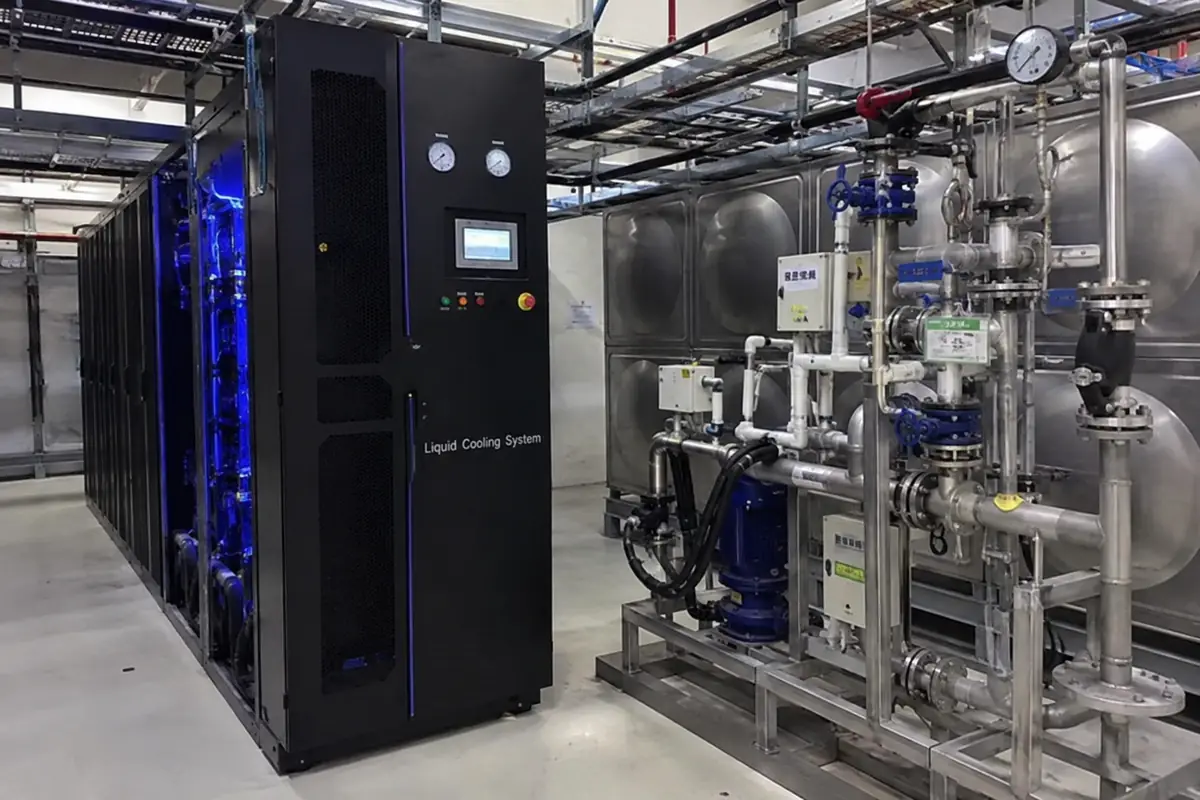
When we receive a request for a “1 MW liquid cooling system,” the stated capacity is only the starting point.
A 1 MW quotation may cover a single CDU, or it may include rack manifolds, pumps, facility-side piping, dry coolers, controls and commissioning. Different suppliers may also rate their equipment at different coolant temperatures, flow rates and pressure drops.
Without a common technical and commercial basis, the lowest quotation may simply have the narrowest scope.
A practical data center liquid cooling RFQ should allow us to determine:
- how much heat must be removed by liquid;
- what operating conditions the system must meet;
- which equipment is included in our supply;
- what level of redundancy is required;
- how performance will be tested and accepted;
- how the quotation should be structured.
The RFQ does not need to contain a completed liquid cooling design. It needs enough information for us to select the system without relying on assumptions that could later affect capacity, cost or delivery.
What Information Should Be Included in a Liquid Cooling RFQ?
For an initial technical review, we normally need the following information:
| RFQ Section | Required Information |
|---|---|
| Project | Location, project stage, application and commissioning date |
| IT deployment | Server model, rack quantity, rack load and expansion plan |
| Cooling duty | Liquid-side design load and residual air-side heat |
| TCS | Temperatures, coolant, flow, pressure drop and water quality |
| FWS | Temperatures, coolant, available flow and pressure |
| Architecture | Rack-mounted, sidecar, in-row, centralized or open for proposal |
| Reliability | Pump/CDU redundancy, power arrangement and acceptable fault domain |
| Controls | BMS protocol, alarms, monitored points and control authority |
| Site | Ambient conditions, altitude, installation space and noise limits |
| Scope | Equipment, piping, coolant, installation and commissioning |
| Acceptance | Performance guarantees, FAT, SAT and documentation |
| Commercial | Price breakdown, exclusions, lead time and warranty |
We recommend requiring every bidder to provide five separate schedules:
- technical compliance;
- assumptions;
- deviations and exclusions;
- guaranteed performance;
- itemized pricing.
This format makes quotations easier to compare and reduces the risk of discovering missing scope after supplier selection.
1. Define the Project Stage Before Requesting a Firm Price
The first page of the RFQ should explain what the quotation will be used for.
A feasibility estimate cannot carry the same commercial certainty as a procurement quotation based on an approved design. When the project stage is unclear, suppliers may price different levels of engineering, testing and risk.
| RFQ Stage | Appropriate Supplier Response |
|---|---|
| Budgetary evaluation | Preliminary architecture, utility requirements, footprint, assumptions and budget price |
| Design development | Equipment selection, preliminary drawings, controls concept and detailed pricing |
| Procurement | Firm price, guaranteed performance, test plan, compliance statement and delivery schedule |
| Expansion project | Compatibility review, additional equipment, shutdown requirements and revised controls |
We suggest marking important data as:
- Confirmed: approved by the owner, consultant or IT equipment manufacturer;
- Preliminary: suitable for quotation but subject to final confirmation;
- Supplier to propose: the bidder should recommend the value or arrangement;
- By others: outside the supplier’s scope but relevant to system coordination.
A preliminary figure is usually more useful than an empty field because it gives us a defined basis for the quotation.
The project summary should also identify:
- greenfield, retrofit or expansion;
- AI, HPC, cloud, edge or mixed workload;
- Phase 1 and final deployment capacity;
- required equipment delivery date;
- target commissioning date;
- applicable destination standards;
- whether alternative proposals are permitted.
Where alternatives are allowed, we recommend requesting a compliant base quotation first. Alternative arrangements can then be evaluated without losing the common comparison basis.
2. Build the Cooling Duty From the Rack Schedule
We do not recommend sizing a CDU from total facility power alone.
The design should begin with the server and rack schedule because heat density, liquid capture ratio, flow demand and pressure drop can vary significantly between rack types.
For each server or rack configuration, provide:
- server manufacturer, model and configuration;
- number of servers per rack;
- expected and maximum rack power;
- percentage of heat transferred to liquid;
- coolant supply and return temperature limits;
- required flow per server or rack;
- pressure drop at the stated flow;
- maximum allowable coolant pressure;
- hose, quick-disconnect and manifold details;
- remaining heat released into the room.
The following values should be listed separately:
| Load Value | Purpose |
|---|---|
| Installed IT capacity | Maximum installed electrical reference |
| Expected operating load | Part-load operation and energy analysis |
| Maximum concurrent load | Main system design basis |
| Liquid-side heat load | CDU and TCS capacity |
| Residual air-side heat | Room air-cooling requirement |
| Future expansion load | Header, equipment and space planning |
| Critical load after failure | Redundancy calculation |
A design margin, future expansion allowance and N+1 redundancy are not the same thing. Combining them into one oversized capacity figure makes it difficult to evaluate whether the proposed system is correctly selected.
For a preliminary water calculation:
Cooling capacity (kW) ≈ 1.163 × flow (m³/h) × temperature rise (°C)
The final calculation should use the actual coolant properties. Glycol concentration and operating temperature affect specific heat, density, viscosity, system pressure loss and pump power.
A clear CDU duty statement should therefore look like this:
1,200 kW heat-transfer capacity at the specified TCS and FWS temperatures, with 103 m³/h TCS flow, 220 kPa external pressure drop, defined coolant chemistry and stated redundancy.
It should not simply say:
1.2 MW CDU.
Our guide on how to size a CDU for data center liquid cooling explains the relationship between heat load, temperature difference, flow, pressure drop and redundancy in more detail.
3. Specify TCS and FWS Conditions Separately
The Technology Cooling System and Facility Water System perform different functions.
The TCS circulates coolant through the server-side loop. The FWS receives heat through the CDU heat exchanger and transfers it to a dry cooler, cooling tower, chiller or another heat-rejection system.
These two loops may use different fluids, pressures, water-quality limits and wetted materials.
Technology Cooling System Data
For the TCS, provide:
- design heat load;
- supply and return temperatures;
- design flow;
- external system pressure drop;
- coolant type and concentration;
- water-quality requirements;
- approved and prohibited wetted materials;
- filtration rating;
- maximum operating pressure;
- system fluid volume, if known;
- responsibility for expansion, degassing, filling and draining.
Descriptions such as “clean water” or “treated water” are not sufficient unless the RFQ also identifies measurable limits or refers to the server manufacturer’s coolant specification.
We also recommend separating:
- circulating pressure loss;
- CDU internal pressure loss;
- system static pressure;
- maximum allowable working pressure;
- maximum allowable pressure at the cold plates and quick disconnects.
For pump evaluation, request the proposed operating point on the pump curve. Maximum pump flow and maximum pump head do not represent the same operating condition.
Facility Water System Data
For the FWS, provide:
- entering and leaving temperatures at the CDU;
- available flow;
- available differential pressure;
- coolant and glycol concentration;
- allowable pressure drop;
- facility water quality;
- pump and piping responsibilities;
- connection size and type;
- part-load operating conditions;
- operating conditions after a defined equipment failure.
We cannot confirm CDU heat-exchanger performance using TCS data alone. The final capacity depends on the temperature relationship between the TCS and FWS, as well as flow and coolant properties on both sides.
Where outdoor heat rejection is included, the RFQ should also contain:
- summer design dry-bulb temperature;
- winter minimum temperature;
- altitude;
- dust, salt or corrosive exposure;
- maximum noise level;
- available installation space;
- airflow and service-clearance restrictions.
The CDU and dry cooler must be selected using the same FWS load, temperature, flow, coolant and redundancy conditions. Our dry cooler sizing guide for liquid-cooled data centers explains the main selection variables.
4. Define the Supply Boundary Clearly
The phrase “complete liquid cooling system” can mean different things to different bidders.
A direct-to-chip cooling path may include:
Cold plates → server hoses → quick disconnects → rack manifolds → TCS piping → CDU → FWS piping → outdoor heat-rejection equipment
The RFQ should assign responsibility for every section of this path.
| System Item | Scope to Define |
|---|---|
| Cold plates, hoses and QDs | IT vendor, owner or liquid cooling supplier |
| Rack manifolds | Included, excluded or optional |
| TCS branch and main piping | Supplier or MEP contractor |
| CDU package | Equipment and internal controls |
| FWS pumps and piping | Supplier or facility scope |
| Dry cooler or other heat rejection | Included, excluded or separate package |
| Expansion and degassing | Equipment or project scope |
| Initial coolant and filters | Included or by others |
| Pipe insulation | Factory and field responsibilities |
| Leak detection | Local package, room system or both |
| BMS integration | Hardware, programming and point-to-point testing |
| Installation and commissioning | Included, supervised or by others |
For every battery limit, define:
- connection location;
- pipe size;
- connection standard;
- temperature and pressure;
- isolation-valve responsibility;
- flexible-connection responsibility;
- insulation termination;
- required cleanliness condition at handover.
The RFQ should also identify the residual air-cooling requirement. Direct-to-chip cooling may remove most of the processor heat, while memory, storage, networking devices and power supplies still release heat into the data hall.
Where the project requires coordinated racks, liquid cooling, power distribution, monitoring and fire protection, an integrated liquid-cooled data center micro module may be more appropriate than purchasing separate CDU packages.
5. Define Architecture, Redundancy and Fault Domain
The preferred CDU architecture may be:
- rack-mounted;
- sidecar;
- in-row;
- centralized;
- divided into multiple independent cooling zones.
The decision affects rack space, floor space, pipe routing, maintenance access, hydraulic balancing, future expansion and the amount of IT load exposed to one equipment failure.
Our comparison of rack-mounted, sidecar and in-row CDUs explains the main trade-offs.
The RFQ should not state only “N+1 required.” It should define what must remain operating under specific failure conditions.
Ask each bidder to explain the system response when:
- one TCS pump fails;
- one complete CDU is isolated;
- one electrical feed is lost;
- one controller or temperature sensor fails;
- BMS communication is interrupted;
- FWS flow is lost;
- a coolant leak is detected;
- utility power is restored;
- one dry cooler becomes unavailable.
Pump redundancy does not automatically provide CDU redundancy. A package with duty and standby pumps may still have a common heat exchanger, controller, electrical panel, filter or main valve.
The RFQ should therefore define the acceptable fault domain:
How many racks, or how many kilowatts of IT load, may lose liquid cooling when one complete CDU or cooling train is unavailable?
This is more useful than a general redundancy label.
6. Specify Controls and Guaranteed Performance
AI and HPC workloads can change quickly. The system must be able to maintain stable temperature and differential pressure as racks are loaded, unloaded or added to the loop.
Ask the supplier to declare:
- minimum stable flow;
- minimum stable heat load;
- pump and valve turndown;
- allowable temperature variation;
- allowable differential-pressure variation;
- response to a defined load step;
- multi-CDU lead/lag or group-control logic;
- behavior after sensor, communication or power failure;
- automatic restart sequence.
For BMS integration, specify:
- Modbus TCP, Modbus RTU, BACnet/IP or another protocol;
- required monitored points;
- alarm routing;
- event-history retention;
- trend-recording interval;
- user access levels;
- whether the BMS has read-only or read/write authority;
- local operating mode after communication loss.
Guaranteed Performance Schedule
Every bidder should complete the same schedule.
| Guaranteed Item | Rating Basis |
|---|---|
| Heat-transfer capacity | Specified TCS/FWS temperatures and coolant |
| TCS design flow | Stated external system pressure drop |
| Pump duty | Flow and differential pressure at one operating point |
| TCS supply temperature | Full design load |
| Heat-exchanger approach | Guaranteed duty condition |
| Maximum electrical input | Agreed full-load condition |
| Minimum stable load | Without unstable cycling |
| Remaining cooling capacity | Defined failure scenario |
| Outdoor-unit capacity | Site ambient, altitude and coolant |
Require suppliers to identify whether each figure is guaranteed, calculated or typical. A catalogue rating at different operating conditions should not be accepted as proof of compliance.
7. Define FAT, SAT and Documentation
“Factory tested” is not a complete acceptance requirement.
Before comparing quotations, define the required Factory Acceptance Test scope.
FAT may include:
- dimensional and visual inspection;
- pressure and leak testing;
- pump operation;
- sensor and alarm checks;
- duty/standby pump changeover;
- communication testing;
- power-loss and restart testing;
- leak-detection response;
- simulated thermal loading.
SAT may include:
- installation inspection;
- flushing and cleanliness verification;
- coolant-quality testing;
- filling and air removal;
- hydraulic balancing;
- BMS point-to-point checks;
- failover testing;
- full-load or simulated-load testing;
- operator training.
The required documentation should normally include:
- general arrangement drawings;
- P&ID;
- equipment datasheets;
- pump curves;
- electrical drawings;
- I/O list;
- sequence of operation;
- FAT and SAT procedures;
- coolant requirements;
- maintenance schedule;
- spare-parts list;
- O&M manuals;
- final as-built documents.
Testing and documentation requirements should be agreed before the order is placed. Adding them after manufacturing has started can affect both price and delivery time.
8. Make the Commercial Quotations Comparable
The RFQ should require separate pricing for:
- base CDU equipment;
- rack manifolds and hoses;
- TCS distribution equipment;
- FWS pumps and piping;
- dry coolers or other heat-rejection equipment;
- controls and BMS integration;
- engineering;
- FAT options;
- packing and freight;
- installation supervision;
- commissioning;
- initial coolant and filters;
- start-up and operating spares;
- training;
- warranty and service.
Before comparing total prices, normalize:
- heat-transfer duty;
- flow and pressure drop;
- TCS and FWS temperatures;
- coolant;
- system boundary;
- redundancy;
- outdoor design condition;
- controls;
- testing;
- commissioning;
- delivery terms.
A lower quotation may represent an efficient solution. It may also exclude manifolds, piping, pumps, dry coolers, coolant, BMS integration or commissioning.
Copy-and-Use Liquid Cooling RFQ Data Sheet
| RFQ Field | Project Data |
|---|---|
| Project location and stage | __________ |
| Server manufacturer and model | __________ |
| Phase 1 rack quantity | __________ |
| Final rack quantity | __________ |
| Expected rack load | __________ kW |
| Maximum rack load | __________ kW |
| Liquid heat-capture ratio | __________ % |
| Liquid-side design load | __________ kW |
| Residual air-side load | __________ kW |
| TCS supply / return | __________ / __________ °C |
| TCS coolant | __________ |
| TCS design flow | __________ m³/h |
| External pressure drop | __________ kPa |
| Maximum TCS pressure | __________ kPa |
| FWS supply / return | __________ / __________ °C |
| FWS coolant | __________ |
| Available FWS pressure | __________ kPa |
| Outdoor design temperature | __________ °C |
| Site altitude | __________ m |
| Preferred CDU architecture | __________ |
| Redundancy requirement | __________ |
| Critical load after one failure | __________ kW |
| BMS protocol | __________ |
| Required supply boundary | __________ |
| FAT / SAT requirement | __________ |
| Expansion capacity | __________ kW |
| Delivery destination and date | __________ |
For an early budget quotation, we can normally begin with:
Project location + server model + rack quantity + rack-load range + liquid-side heat load + TCS temperatures + estimated pressure drop + FWS or outdoor conditions + redundancy requirement + requested supply boundary.
Frequently Asked Questions
Can we prepare a quotation before the final server model is confirmed?
Yes. At the budgetary stage, provide the expected rack-load range, likely TCS temperature range, estimated liquid heat-capture ratio and planned rack quantity. We will identify which assumptions must be confirmed before final equipment selection.
What is the minimum information required for a CDU quotation?
The main inputs are liquid-side heat load, TCS temperatures, coolant, flow, external pressure drop, FWS conditions and redundancy. Rack quantity and layout are also needed to determine the appropriate CDU architecture.
Is 20% spare capacity the same as N+1 redundancy?
No. Spare capacity does not protect the project if the only CDU becomes unavailable. N+1 should be evaluated against the critical load that must remain cooled after one complete unit or cooling train is isolated.
Should the CDU and dry cooler be included in the same quotation?
They can be purchased separately, but both packages must use the same FWS load, flow, temperatures, coolant, pressure drop and redundancy basis. A coordinated package can reduce responsibility gaps between the indoor and outdoor systems.
Order & Project Support
A reliable data center liquid cooling system RFQ follows a clear sequence:
Rack data → liquid-side heat load → TCS duty → hydraulic duty → FWS conditions → heat rejection → architecture → redundancy → controls → testing → commercial scope.
For a project-specific review, contact us with your server and rack schedule, TCS and FWS conditions, project location, redundancy target, deployment plan and required supply boundary.
You can submit the available information through our liquid cooling project consultation page. Preliminary data is sufficient for an initial proposal. We will identify the parameters that need to be confirmed before final system selection and production.