

How to Retrofit an Existing Data Center for Liquid Cooling Without a Full Rebuild

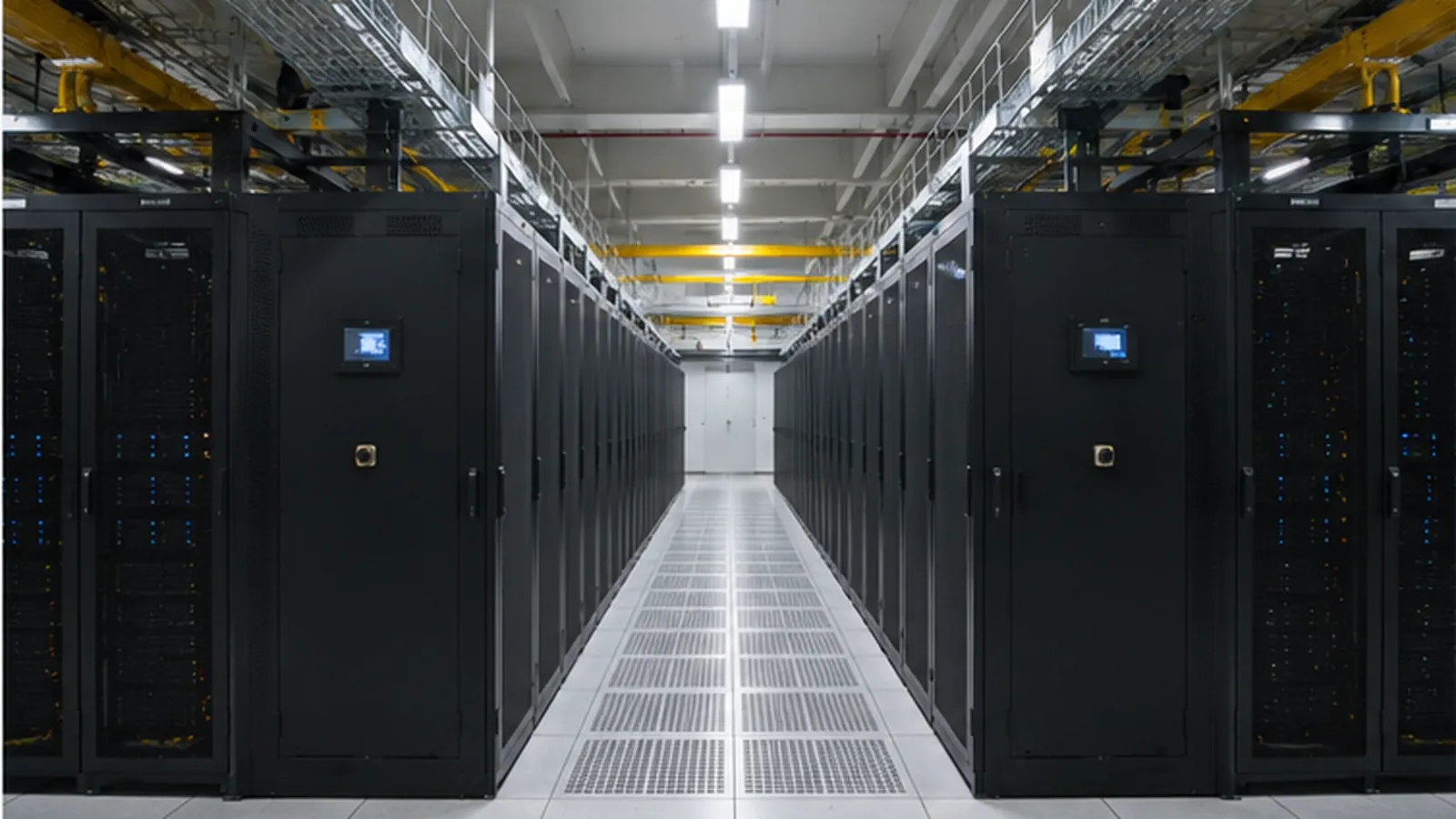
Retrofitting an operating data center for liquid cooling is rarely a “replace the cooling system” project. In most cases, the better objective is to keep the infrastructure that can still support the new load, add liquid cooling where it is needed, and avoid unnecessary changes to the rest of the facility.
That is why we do not begin a data center liquid cooling retrofit by selecting a CDU. We first check whether the existing site can support the planned high-density racks from five directions: power, cooling, structure, space and operations.
A data hall may have enough chiller capacity but no practical route for new liquid headers. Another may have suitable facility water but insufficient electrical capacity at the rack. A third may support the first four GPU racks but not the planned 20-rack expansion.
The retrofit design has to solve the actual constraint, not simply add more cooling equipment.
1. First Decide Whether the Existing Facility Is Retrofit-Ready
Before equipment selection, we normally establish the limits of the existing data center.
| Area | What to Verify | Why It Matters |
|---|---|---|
| Power | Rack power, PDU/UPS capacity, distribution path, future load | High-density racks may exceed the original electrical design |
| Cooling | Existing plant capacity, water temperatures, flow, pressure, residual air cooling | Determines whether existing cooling can be reused |
| Structure | Rack weight, floor loading, CDU weight, pipe support | AI racks and cooling equipment can change structural loads |
| Space | Rack layout, aisle width, CDU location, pipe routes, maintenance access | A technically correct system can still be difficult to install |
| Operations | Shutdown windows, live-site work rules, redundancy, migration sequence | Determines how the retrofit can be phased |
Cooling capacity alone does not determine whether a retrofit is practical.
For example, an older hall designed around lower-density racks may still have available central cooling capacity, but deploying 80–120 kW racks can also require changes to busways, PDUs, branch circuits, pipe routes, floor loading and service clearances.
We therefore treat liquid cooling as one part of the retrofit rather than as an isolated mechanical package.
2. Calculate the Liquid Load, Not Just Total IT Load
The first thermal number we want is the load that will actually enter the liquid loop.
With direct-to-chip cooling, not all server heat necessarily goes into the coolant. Power supplies, memory, storage, network equipment and other components may still reject heat to the room.
For preliminary planning:
Liquid Cooling Load = IT Load × Liquid Heat-Capture Ratio
Consider 12 racks rated at 120 kW each with 90% of the heat transferred to liquid:
- Total IT load: 1,440 kW
- Liquid-side load: 1,296 kW
- Residual air-side load: approximately 144 kW
The CDU should therefore not be specified simply as a “1.44 MW CDU.”
We still need the required TCS supply and return temperatures, coolant type, flow, system pressure drop and facility-side conditions. These parameters are covered in more detail in our How to Size a CDU for Data Center Liquid Cooling guide.
The residual 144 kW also matters. It is one reason we do not recommend removing existing CRAH or CRAC capacity simply because liquid cooling has been installed.
3. Choose the Retrofit Route From the Existing Cooling Infrastructure
One of the most useful early decisions is whether the site has a Facility Water System that can support a liquid-to-liquid CDU.
| Existing Facility Condition | Practical Retrofit Direction |
|---|---|
| Suitable facility water is available | Liquid-to-liquid CDU + separate TCS loop |
| No suitable facility water, but room air cooling has spare capacity | Liquid-to-air CDU for an initial or limited liquid-cooled zone |
| Existing chilled-water plant has spare capacity | Reuse after verifying temperature, flow, pressure and controls |
| Existing cooling plant cannot absorb the new load | Independent CDU + heat-rejection loop |
| Only a few racks require liquid cooling | Rack-mounted or local sidecar CDU |
| A complete AI/HPC row will be converted | In-row or larger shared CDU |
| Legacy air-cooled racks will remain | Hybrid air-and-liquid-cooled data hall |
| Expansion will occur in phases | Reserve headers, isolation points and CDU space for final capacity |
This decision is more useful than starting with a CDU capacity range.
Liquid-to-Liquid Retrofit
Where suitable facility water is available, a liquid-to-liquid CDU provides hydraulic separation between the Facility Water System (FWS) and the Technology Cooling System (TCS) serving the servers.
The existing chilled-water or facility loop may be reusable, but we do not assume this before checking its actual operating condition.
A plant can have enough nominal cooling capacity yet still be unsuitable because of:
- FWS supply and return temperatures;
- available differential pressure;
- insufficient flow;
- water quality;
- pump limitations;
- control behavior at the new operating point.
We also check how any change in facility-water temperature affects the air-cooled areas that remain in operation.
A mixed facility may require separate cooling zones rather than forcing existing CRAHs and the new liquid-cooled racks to operate around one water temperature.
Liquid-to-Air Retrofit
If there is no practical facility-water connection, a liquid-to-air CDU can be considered for a limited retrofit.
Instead of transferring server heat into facility water, it transfers that heat from the liquid loop back into the data-hall air.
This can reduce facility-water piping work and may suit an initial AI deployment, but it does not eliminate the heat. The existing air-conditioning system must still have sufficient capacity to remove it.
For larger deployments, this approach can therefore become constrained by the same room air-cooling capacity that the project is trying to overcome.
4. Match CDU Architecture to Rack Count and Expansion
For an existing data center, CDU location can affect installation difficulty almost as much as CDU capacity.
Rack-Mounted CDU
A rack-mounted CDU is often practical when only a small number of racks are being converted.
The coolant path remains short, and racks can be brought onto liquid cooling relatively independently.
It is most suitable when:
- only one or several racks require liquid cooling;
- rack-level modularity is important;
- short TCS piping is preferred;
- sufficient rack U-space is available.
The limitation is scale.
As rack count or heat density increases, multiple small CDUs also mean more pumps, filters, controls and maintenance points.
Enclosure-Side / Sidecar CDU
For several adjacent high-density racks, an enclosure-side CDU moves the cooling equipment outside the IT rack while keeping it close to the load.
This preserves server U-space and provides room for larger pumps and heat exchangers without immediately moving to a fully centralized system.
In-Row CDU
When an entire AI/HPC row or a larger rack group is being converted, an in-row CDU can reduce the number of separate cooling packages and provide higher centralized capacity.
The trade-off is that header sizing, hydraulic balancing, branch isolation and failure-domain planning become more important.
Our Rack-Mounted vs Sidecar vs In-Row CDU comparison covers the equipment-level differences in more detail.
For retrofit work, however, we normally select the architecture around the final rack plan, not only Phase 1.
A cooling arrangement that looks simple for four racks can become unnecessarily complicated when that zone later grows to 20 racks.
5. Reuse Existing Cooling Equipment Only After Checking Its New Duty
One of the main opportunities in a brownfield data center is reuse.
One of the main risks is assuming reuse is always possible.
Existing chillers, pumps, cooling towers, dry coolers and distribution pipework should be checked at the new temperature and flow conditions.
For the facility side, we normally review:
- heat-rejection capacity at peak load;
- FWS supply and return temperature;
- required flow;
- pump head and available differential pressure;
- partial-load operation;
- redundancy;
- water or glycol concentration;
- control-valve operation;
- future expansion margin.
Warmer liquid-cooling temperatures may create opportunities for economization or direct heat rejection, but the complete cooling chain has to support those temperatures.
Where the existing plant cannot accept the additional liquid load, a dedicated data center dry cooler may provide an independent heat-rejection path.
Dry cooler selection should be based on actual FWS temperatures, design ambient temperature, coolant concentration and required flow rather than a nominal “MW” rating alone.
6. Design the Pipe Route Before Final CDU Selection
In a retrofit, piping is often one of the most difficult parts of the project.
A new data center can place headers where the mechanical design requires them. An operating facility has to work around:
- cable trays;
- busways;
- fire protection;
- existing chilled-water pipes;
- containment;
- access routes;
- live IT equipment.
Before final CDU selection, we want a realistic route for:
- FWS supply and return;
- TCS mains;
- rack branches;
- manifolds;
- isolation valves;
- drains and vents;
- flexible hoses and quick disconnects.
Pipe length, diameter, elevation, fittings, valves, filters, manifolds and server-side components all contribute to pressure drop.
A CDU can have sufficient heat-transfer capacity and still be incorrectly selected if its pumps cannot maintain the required flow through the actual system resistance.
We also prefer to create practical isolation zones.
Where possible, one rack, manifold or row should be serviceable without draining or shutting down a much larger part of the liquid cooling system.
7. Do Not Remove Air Cooling Before the Residual Load Is Proven
A common retrofit mistake is assuming that direct-to-chip cooling eliminates the data hall’s air-cooling requirement.
It normally reduces that requirement substantially, but the remaining load still needs to be quantified.
Existing CRAHs or CRACs may continue supporting:
- non-liquid-cooled server components;
- network and storage equipment;
- legacy racks;
- electrical equipment;
- room environmental control.
Instead of removing air cooling immediately, we normally recommend commissioning the liquid-cooled zone first and observing the resulting air-side load.
CRAH/CRAC fan speed or active-unit quantity can then be adjusted as more heat moves into the liquid loop.
This is safer than redesigning the room air system around an assumed heat-capture percentage.
8. Design the Retrofit Around Failure Domains
“N+1 pumps” does not by itself describe the resilience of a liquid cooling system.
For a retrofit, we want to understand what happens when:
- one TCS pump fails;
- one CDU is isolated;
- facility-water flow is lost;
- one electrical feed is unavailable;
- a filter requires service;
- a leak is detected;
- communication with the BMS is interrupted.
A more useful engineering question is:
How many racks—or how many kilowatts of IT load—can lose liquid cooling after one equipment failure?
For larger installations, dividing the deployment into independent cooling zones can reduce the fault domain and make future expansion easier.
This is especially important in existing facilities because the new liquid cooling infrastructure has to work with the redundancy philosophy already used by the data center.
9. Retrofit in Phases Instead of Rebuilding the Hall at Once
Where the data center must remain live, we generally prefer staged conversion.
Phase 1 — Facility Survey
Confirm rack power, liquid load, FWS conditions, pipe routes, structural limits and shutdown restrictions.
Phase 2 — Pilot or First Rack Group
Bring a limited liquid-cooled zone online and verify temperatures, flow, pressure, controls, alarms and operating procedures.
Phase 3 — Main Distribution
Install or extend headers, branch isolation and reserved connections for additional rack groups.
Phase 4 — Capacity Expansion
Add CDU capacity as the IT deployment grows rather than installing unnecessary capacity on day one.
Phase 5 — Air-Side Optimization
Adjust CRAH/CRAC operation after the actual residual heat load is known.
Phase 6 — Cooling Plant Optimization
Tune facility-water temperatures, pumps and heat-rejection equipment around the real liquid-cooled load.
This sequence reduces the amount of work that must be completed during one major shutdown and allows the operations team to validate each stage before the next expansion.
10. What We Need for a Preliminary Retrofit Review
A useful liquid cooling retrofit review does not require a completed mechanical design.
We normally need:
- project location;
- rack layout;
- server model and quantity;
- present and future rack load;
- expected liquid heat-capture ratio;
- server TCS temperature, flow and pressure requirements;
- existing cooling architecture;
- FWS supply and return temperatures;
- available FWS flow and pressure;
- proposed CDU location;
- pipe-route constraints;
- residual air-cooling requirement;
- redundancy target;
- Phase 1 and final cooling load;
- permitted shutdown windows.
If the project has already reached the supplier quotation stage, our How to Prepare an RFQ for a Data Center Liquid Cooling System guide covers the technical inputs, scope boundaries and performance information required for comparable quotations.
Order & Project Support
The best liquid cooling retrofit for an existing data center is not necessarily the one that replaces the most infrastructure.
A better project identifies what can remain, what must change and how the new TCS can be introduced without creating unnecessary risk for the operating facility.
For a preliminary project review, the most useful starting information is:
rack schedule + server model + present and future IT load + existing cooling architecture + FWS conditions + floor plan + redundancy requirement + expansion plan
From those inputs, we can evaluate whether the project is better suited to a localized liquid-to-air approach, an FWS-connected liquid-to-liquid CDU, or a larger independent liquid cooling loop with dedicated heat rejection.