

How to Size a CDU for Data Center Liquid Cooling

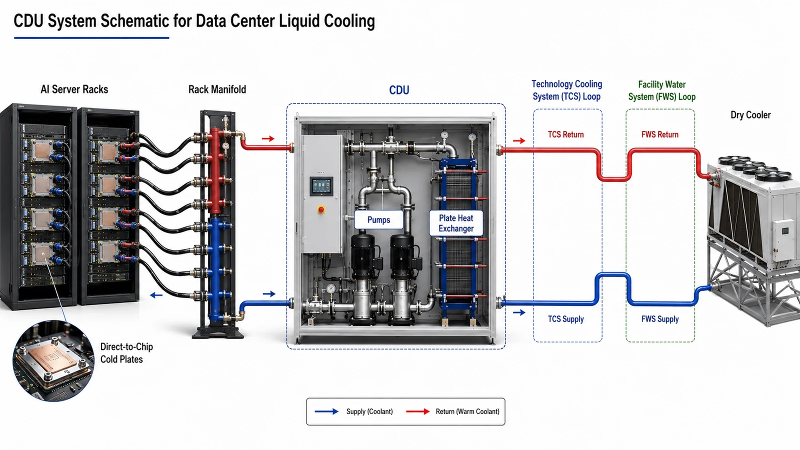
Selecting a Coolant Distribution Unit (CDU) for an AI or high-density data center involves more than matching the CDU’s rated cooling capacity to the total IT load.
A 1 MW IT deployment does not automatically require a CDU simply labeled “1 MW.” The selected unit must also provide the required coolant flow at the actual system pressure drop, maintain the target supply temperature under available facility-water conditions, support the specified coolant, and meet the project’s redundancy requirements.
For preliminary engineering, CDU sizing can be approached through the following sequence:
IT load → liquid heat load → TCS temperature range → ΔT → coolant flow → pressure drop → CDU duty point → redundancy → heat rejection
This guide explains how to work through those steps and what information should be prepared before requesting a CDU quotation.
1. Start With the Actual Liquid Cooling Load
The first step is determining how much heat will actually enter the liquid cooling loop.
Assume a data center contains:
- 24 AI racks
- 100 kW maximum IT load per rack
The maximum installed IT load is:
24 × 100 kW = 2,400 kW
However, direct-to-chip liquid cooling does not necessarily capture 100% of server heat. CPUs and GPUs may be connected to cold plates while memory, power supplies, storage and other components may still reject part of their heat to air.
The preliminary liquid-side load can therefore be calculated as:
Liquid Cooling Load = IT Load × Liquid Heat-Capture Ratio
If server thermal data shows that 90% of the heat enters the liquid loop:
2,400 kW × 90% = 2,160 kW
The preliminary CDU system must therefore handle approximately 2.16 MW of liquid-side heat.
The liquid heat-capture ratio should come from the server or rack manufacturer whenever possible. It should not be assumed to be the same for every AI platform.
Do not combine every design margin into one number
It is useful to separate:
- installed IT capacity;
- expected operating load;
- design liquid cooling load;
- future expansion capacity;
- redundancy requirements.
These represent different engineering considerations. Adding an arbitrary 20% or 30% to every stage can result in unnecessary oversizing.
2. Use ΔT to Calculate the Required Coolant Flow
Once the liquid heat load is known, the next major parameter is coolant flow.
For a liquid cooling loop:
Q = ṁ × Cp × ΔT
For preliminary calculations using water near common data center operating temperatures, a convenient approximation is:
Cooling Capacity (kW) ≈ 1.163 × Flow (m³/h) × ΔT (°C)
Therefore:
Flow (m³/h) ≈ Cooling Capacity (kW) ÷ [1.163 × ΔT]
Example: 2.16 MW at 10°C ΔT
Assume the Technology Cooling System (TCS) operates at:
- TCS supply: 35°C
- TCS return: 45°C
- ΔT: 10°C
The required preliminary water flow is:
2,160 ÷ (1.163 × 10) ≈ 186 m³/h
The preliminary duty is therefore approximately:
2,160 kW at 186 m³/h with a 10°C coolant temperature rise.
If the same project operates at only 5°C ΔT, required flow increases to approximately 371 m³/h.
| Liquid Cooling Load | Flow at 5°C ΔT | Flow at 10°C ΔT |
|---|---|---|
| 100 kW | 17.2 m³/h | 8.6 m³/h |
| 500 kW | 86.0 m³/h | 43.0 m³/h |
| 1,000 kW | 172.0 m³/h | 86.0 m³/h |
| 2,160 kW | 371.5 m³/h | 185.7 m³/h |
This is one reason CDU specifications should always be evaluated using capacity, flow and temperature conditions together.
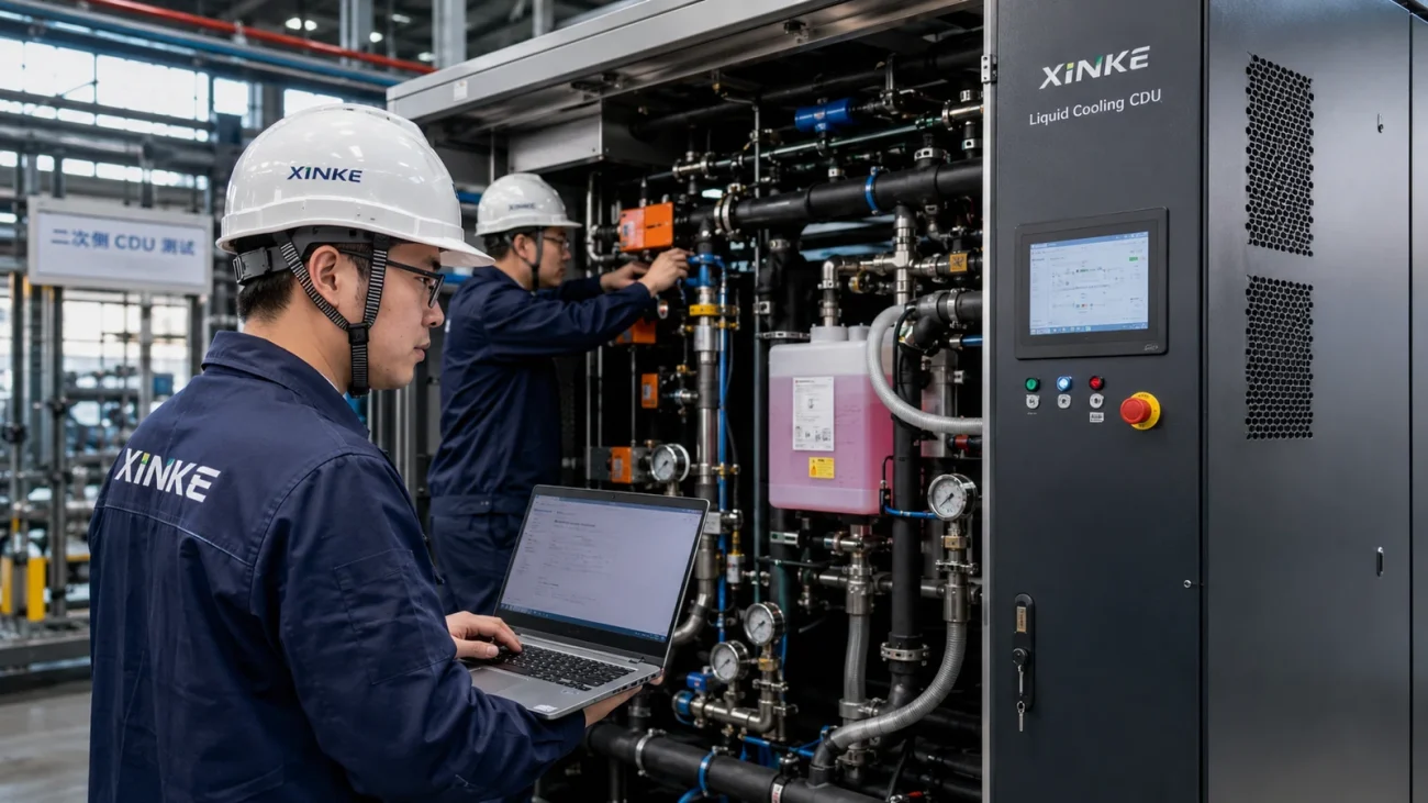
For smaller rack-level applications, XINKE LCS offers a Rack-Mounted CDU for Data Center Liquid Cooling, while larger local cooling loads can be handled with an Enclosure-Side CDU.
What changes when glycol is used?
The water formula above is suitable for preliminary estimates only.
Ethylene glycol, propylene glycol and other coolant mixtures have different:
- specific heat;
- density;
- viscosity;
- pressure loss;
- heat-transfer performance.
Final sizing should therefore use the actual coolant type, concentration and operating temperature.
3. Cooling Capacity Alone Is Not Enough: Check Pressure Drop
A CDU can have sufficient heat-transfer capacity and still be unsuitable if its pumps cannot deliver the required flow through the complete liquid circuit.
Pressure losses can occur through:
- server cold plates;
- quick-disconnect couplings;
- rack manifolds;
- flexible hoses;
- filters and strainers;
- control and isolation valves;
- distribution headers;
- pipes, elbows and fittings;
- the CDU heat exchanger.
The pump must therefore be selected against the required flow and differential pressure at the same operating point.
For example, assume the previous 2.16 MW project requires:
186 m³/h at 250 kPa
A pump advertised with a “maximum flow of 200 m³/h” is not automatically suitable. The question is whether it can deliver approximately 186 m³/h when the system is imposing 250 kPa of resistance.
Final pump selection should review the pump curve together with the calculated system resistance curve.
Important hydraulic parameters include:
- design flow;
- required pump head;
- maximum TCS operating pressure;
- minimum stable operating flow;
- variable-speed control range;
- pump redundancy;
- allowable pressure at server cold plates and quick disconnects.
A practical CDU therefore has to satisfy two separate requirements:
Thermal duty + hydraulic duty.
4. Check TCS and Facility Water Temperatures
In an indirect liquid cooling system, it is useful to distinguish between two loops.
Technology Cooling System (TCS)
The TCS is the liquid circuit serving the IT equipment. Depending on the architecture, it may include cold plates, rack manifolds, hoses, distribution piping and CDU circulation components.
Facility Water System (FWS)
The Facility Water System receives heat through the CDU heat exchanger and transfers it toward equipment such as dry coolers, cooling towers, chillers or integrated cooling stations.
A project should therefore define at least:
- TCS supply temperature;
- TCS return temperature;
- FWS supply temperature;
- FWS return temperature.
Suppose the TCS requires 35°C supply water. The FWS entering the CDU normally needs to be sufficiently colder than 35°C to maintain a usable temperature difference across the heat exchanger.
The exact temperature approach depends on:
- heat exchanger size;
- TCS and FWS flow;
- coolant properties;
- heat load;
- fouling allowance.
This is why the CDU should be verified at the project’s real TCS and FWS conditions rather than selected only from nominal cooling capacity.
5. Never Compare CDU Ratings Without the Duty Conditions
Two suppliers may both offer a “1,000 kW CDU,” but those units cannot be considered equivalent until their rating conditions are compared.
A CDU rating should ideally identify:
| Parameter | What to Check |
|---|---|
| Cooling capacity | Rated kW at specified conditions |
| TCS supply / return | Actual operating temperatures |
| TCS flow | Required m³/h or L/min |
| FWS supply / return | Heat exchanger operating conditions |
| Coolant | Water, glycol mixture or specified fluid |
| Pump duty | Flow at required differential pressure |
| Maximum pressure | Compatibility with servers and piping |
| Redundancy | Pump redundancy or complete CDU redundancy |
For larger AI and HPC clusters, XINKE’s High-Power In-Row CDU range provides higher-capacity configurations for centralized multi-rack cooling. The final model should still be selected against the actual thermal and hydraulic duty point.
6. Capacity Margin, Redundancy and Expansion Are Not the Same
Three terms are often mixed together during CDU selection:
Capacity Margin
A limited margin may be included to account for operating uncertainty or changes between calculated and actual loads.
Redundancy
Redundancy ensures required cooling remains available when equipment is being maintained or has failed.
Future Expansion
Expansion capacity allows additional racks or compute nodes to be added later.
A 20% capacity margin does not automatically provide N+1 redundancy.
For example, if the required liquid cooling load is 2.0 MW and one 2.4 MW CDU is installed, the system has additional thermal capacity. However, if that CDU is offline, available CDU capacity becomes zero.
Pump redundancy also should not be confused with CDU-level redundancy. A CDU with duty and standby pumps may remain operational after a pump failure, but common components such as the heat exchanger, controller, electrical panel or main valves can still become single points of failure.
Mission-critical projects should therefore define exactly what must remain operational if one pump or one complete CDU is isolated.
7. Rack-Mounted, Sidecar or In-Row CDU?
The physical CDU architecture should follow the required cooling capacity, rack layout and redundancy strategy.
| CDU Type | Typical Application | Main Advantage | Key Design Check |
|---|---|---|---|
| Rack-Mounted CDU | Single rack or small localized loads | Short piping and modular deployment | Rack space, flow and service access |
| Enclosure-Side CDU | One or several high-density racks | Higher local capacity without using rack U-space | Floor space and piping arrangement |
| In-Row CDU | Large AI/HPC rack groups | Higher capacity and centralized control | Header design, zoning and redundancy |
| Parallel CDUs | Large or mission-critical deployments | Scalability and CDU-level redundancy | Hydraulic balancing and sequencing |
Do not select the architecture simply according to which model has the highest cooling capacity. Consider where the CDU will be installed, how piping will be routed, how maintenance will be performed and how future racks will be connected.
8. The CDU and Heat-Rejection System Must Be Sized Together
The CDU transfers heat from the IT loop to the facility loop. It does not reject that heat directly to the outdoor environment.
The complete thermal path may look like:
Server → Cold Plate → TCS → CDU → FWS → Dry Cooler → Ambient Air
That means a correctly sized CDU can still fail to maintain server temperatures if the outdoor heat-rejection system is undersized.
A Data Center Dry Cooler should be selected using the real site conditions, including:
- maximum outdoor design temperature;
- FWS entering and leaving temperatures;
- fluid type and glycol concentration;
- required approach temperature;
- altitude;
- required redundancy.
A dry cooler rated at 1 MW under one set of conditions may deliver substantially different capacity when outdoor temperature or fluid temperature changes.
CDU and heat-rejection sizing should therefore be completed as one coordinated system design.
9. Worked CDU Sizing Example
Consider a preliminary AI computing project with the following conditions:
| Design Input | Example Value |
|---|---|
| Rack quantity | 24 |
| Maximum load per rack | 100 kW |
| Total IT load | 2,400 kW |
| Liquid heat capture | 90% |
| Liquid cooling load | 2,160 kW |
| TCS supply / return | 35 / 45°C |
| ΔT | 10°C |
| Calculated water flow | ≈186 m³/h |
| Example system pressure drop | 250 kPa |
The preliminary CDU requirement is therefore not simply:
“2.16 MW CDU.”
A more useful preliminary specification is:
Approximately 2.16 MW heat-transfer capacity, 186 m³/h TCS flow, 250 kPa required pump differential pressure, 35/45°C TCS conditions, plus verified FWS temperatures and redundancy requirements.
That information gives the CDU manufacturer enough engineering context to begin evaluating:
- heat exchanger size;
- pump configuration;
- CDU quantity;
- parallel arrangement;
- facility-water requirements;
- matching heat-rejection equipment.
10. CDU Sizing & RFQ Checklist
Before requesting a quotation, provide as many of the following parameters as possible:
| Project Parameter | Your Data |
|---|---|
| Project location | ____________ |
| Server / rack model | ____________ |
| Number of racks | ____________ |
| Maximum load per rack | ____________ kW |
| Total liquid cooling load | ____________ kW |
| TCS supply / return temperature | ____________ / ____________ °C |
| Required TCS flow | ____________ m³/h |
| Estimated pressure drop | ____________ kPa |
| Coolant type / concentration | ____________ |
| FWS supply / return temperature | ____________ / ____________ °C |
| Maximum outdoor temperature | ____________ °C |
| Redundancy requirement | ____________ |
| BMS / communication protocol | ____________ |
| Future expansion | ____________ kW |
If server pressure drop, coolant requirements or FWS conditions are still unknown, preliminary capacity sizing can still be performed. Final pump and heat exchanger selection should wait until those parameters are confirmed.
Common CDU Sizing Mistakes
- Using total IT power as CDU load: determine how much heat actually enters the liquid loop.
- Ignoring ΔT: a lower temperature difference can dramatically increase required flow.
- Comparing kW ratings alone: always compare the rating temperatures, fluid and flow.
- Ignoring system pressure drop: pump flow must be verified at the real operating head.
- Confusing capacity margin with redundancy: spare kW does not protect against complete CDU failure.
- Sizing the CDU separately from heat rejection: the FWS and outdoor cooling equipment must accept the same thermal load.
Frequently Asked Questions
How do I calculate the required CDU capacity?
Determine the maximum IT heat load and estimate or obtain the percentage of heat transferred into the liquid circuit. This provides the preliminary liquid-side cooling load. Final CDU capacity must then be checked at the actual TCS and FWS temperature conditions.
How much flow does a 1 MW CDU need?
For water and a 10°C temperature rise, the preliminary flow is approximately 86 m³/h. At a 5°C temperature rise, it increases to approximately 172 m³/h. Actual flow should use the properties of the specified coolant.
Can I size a CDU using only rack power and rack quantity?
You can estimate thermal capacity, but final selection also requires coolant temperatures, fluid type, required flow, system pressure drop and facility-water conditions.
Is a larger CDU always safer?
No. Excessive oversizing can increase capital cost and cause pumps or control valves to operate far from their intended design range. Proper redundancy and modular expansion are usually more useful than uncontrolled oversizing.
Should I use a rack-mounted, sidecar or in-row CDU?
Rack-mounted CDUs are generally suited to smaller localized loads. Sidecar units support higher local capacities without occupying rack U-space, while in-row or parallel CDU systems are typically better suited to larger AI and HPC clusters.
Order & Project Support
Correct CDU sizing for data center liquid cooling should be based on the complete operating duty rather than a single nameplate capacity.
The key relationship is:
Liquid heat load + ΔT + coolant flow + pressure drop + TCS/FWS conditions + redundancy + heat rejection = practical CDU selection.
For a preliminary project review, provide us with your rack quantity, server model, IT load, TCS temperatures, coolant type, estimated pressure drop, FWS conditions and redundancy requirements.
Contact Us for CDU sizing and a project-specific liquid cooling proposal.