

Cold Plate Liquid Cooling System Design for GPU Servers

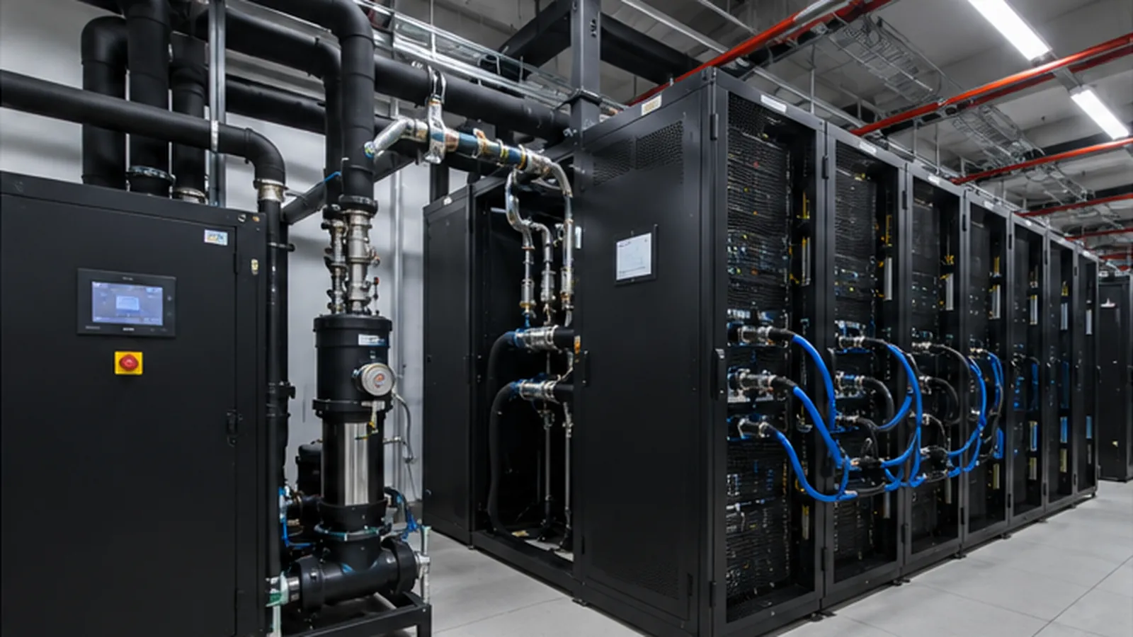
A cold-plate liquid-cooling system for GPU servers should be designed from the server’s thermal and hydraulic requirements outward—not assembled by selecting a CDU, manifolds, and cold plates independently. The goal is a complete heat path that maintains the required coolant condition at every GPU rack while remaining serviceable, controllable, and compatible with the facility water available on site.
Quick answer: start with the approved GPU or server coolant specification, calculate the liquid heat load and required flow, check pressure drop through the installed circuit, select the CDU at that actual duty point, and then confirm the facility-water temperature through the CDU heat-exchanger approach. Capacity alone is not a design.
The same architecture can produce very different results depending on the server platform, rack density, facility climate, maintenance model, and redundancy target. This guide explains the design sequence and the questions to resolve before approving equipment for an AI data center.
1. Collect the server and rack requirements first
The GPU supplier’s approved technical documentation should define the coolant conditions at the actual responsibility boundary—typically the server connection or rack manifold. Do not substitute a generic industry temperature for a platform-specific requirement.
| Design input | Why it is needed |
|---|---|
| Server or GPU model and configured power limit | Defines heat load, coolant limits and pressure constraints |
| Coolant supply and return temperature at the specified boundary | Defines the CDU control target and allowable approach |
| Required flow and maximum pressure | Prevents a thermally adequate system from exceeding hydraulic limits |
| Approved coolant and concentration | Changes specific heat, viscosity, pressure drop and material compatibility |
| Liquid heat-capture ratio | Separates heat removed by coolant from heat rejected to air |
| Rack quantity and maximum load | Establishes the liquid cooling load and future expansion |
Confirm the measurement point in writing. A temperature that is acceptable at the CDU outlet may not satisfy the limit at the last server connection after heat gain and distribution losses.
2. Map the complete liquid-cooling architecture
A direct-to-chip installation normally follows this path:
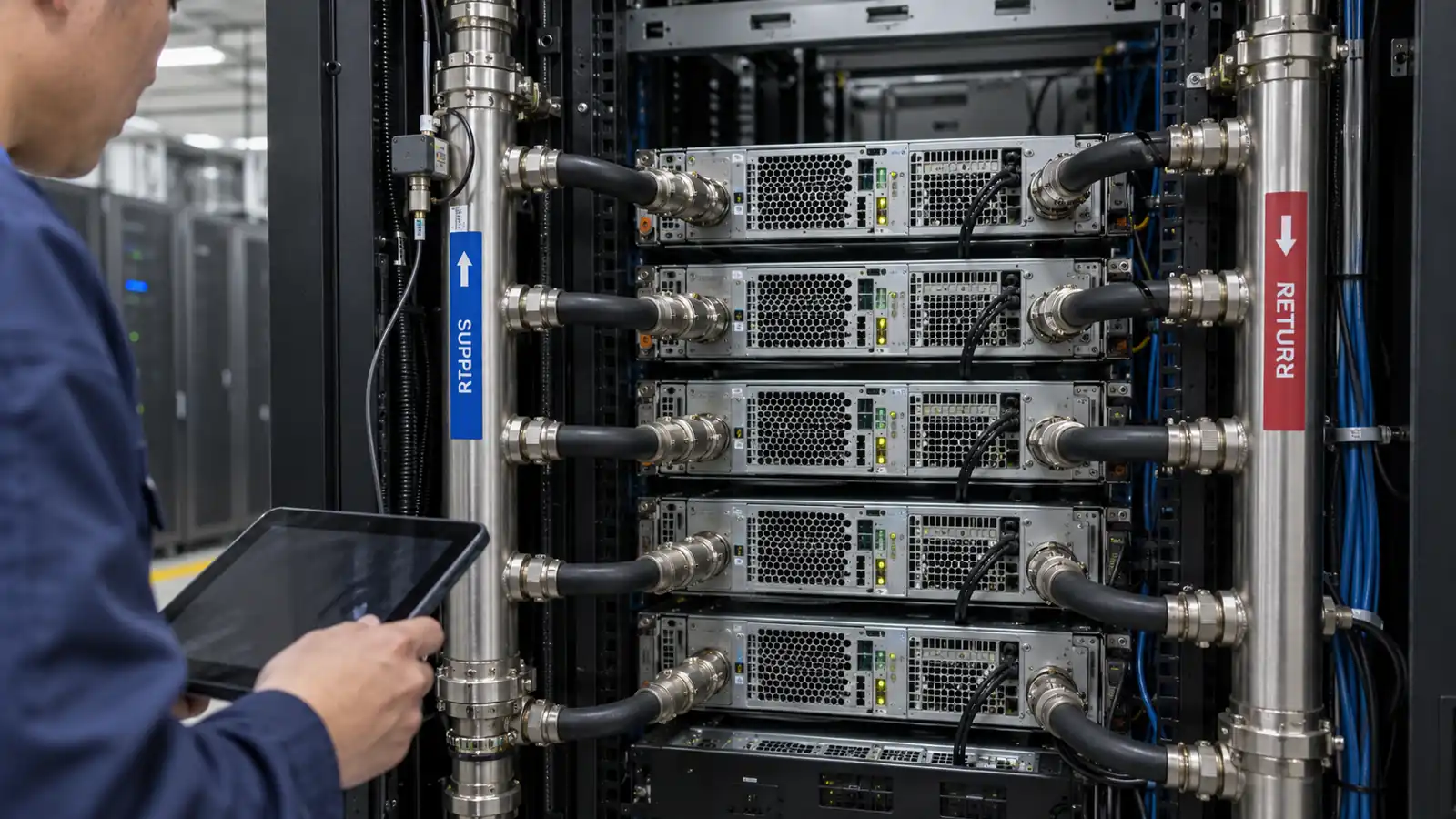
GPU and CPU heat sources → cold plates → rack manifold and quick disconnects → TCS piping → CDU → facility water system → dry cooler, cooling tower or chiller → outdoor environment
The Technology Cooling System (TCS) is the loop serving the IT equipment. The Facility Water System (FWS) transfers heat from the CDU to the facility heat-rejection equipment. The CDU separates the loops and controls the TCS flow, pressure, and temperature.
Use two different perspectives during design. The IT team needs the server-facing conditions to remain within specification. The facilities team needs the CDU to operate within the available facility-water temperature, flow, pressure, and redundancy envelope. The design is complete only when both sets of conditions can be met at the same time.
3. Calculate the liquid heat load and coolant flow
The preliminary liquid-side heat load is:
Liquid heat load = IT load × liquid heat-capture ratio
For water near common data-center temperatures, required flow can be estimated as:
Flow (m³/h) = Liquid heat load (kW) ÷ [1.163 × TCS temperature rise (°C)]
Consider one 100 kW rack with a 90% liquid heat-capture ratio and an 8°C TCS temperature rise:
- Liquid heat load: 100 × 0.90 = 90 kW
- Approximate water flow: 90 ÷ (1.163 × 8) = 9.7 m³/h
The final calculation must use the specified coolant, because glycol mixtures and other fluids have different density, specific heat, and viscosity. The actual heat-capture ratio must also come from the server or rack platform rather than being assumed to be 100%.
A narrower temperature rise requires more flow. This is why a small change to the server coolant specification can materially affect pipe size, pump energy, CDU selection, and the available operating margin.
4. Build a pressure-drop budget before selecting pumps
Every component between the CDU and GPU contributes pressure loss. The pump must deliver the approved flow while overcoming the complete installed circuit at the same time.
- GPU and CPU cold plates
- Server hoses and internal connections
- Quick disconnects and rack manifolds
- Valves, filters, flow meters, and strainers
- Headers, elbows, tees, and secondary piping
- The CDU heat exchanger and internal components
If the calculated duty is 9.7 m³/h at 180 kPa, a pump described only as having a maximum flow above 10 m³/h is not yet proven suitable. The supplier should show the pump curve at the required flow and head, together with the electrical power and operating efficiency.
Also check the maximum pressure permitted by the server, cold plates, quick disconnects, and piping. A robust hydraulic design stays below component limits under pump changeover, valve movement, and maintenance isolation, not only at steady state.
5. Select the CDU at the real flow and pressure duty point
A CDU should be evaluated against the combined thermal and hydraulic requirement:
Required flow + pump head + TCS supply/return temperature + FWS supply/return temperature + coolant + maximum pressure + redundancy
This distinction is important when comparing rack-mounted, enclosure-side, and in-row CDUs. A smaller rack-mounted unit may suit an isolated high-density rack, while a larger AI cluster usually requires a different capacity, redundancy, and service architecture.
XINKE LCS offers rack-mounted CDUs for localized loads, enclosure-side CDUs for higher-density rack groups, and high-power in-row CDUs for larger centralized deployments. The final model should still be selected using the project’s measured duty point; the CDU sizing guide explains the calculation in more detail.
6. Match the facility water temperature to the CDU approach
Facility water does not have to be as cold as the GPU inlet requirement, but it must be cold enough to maintain the TCS setpoint through the CDU heat exchanger while rejecting the design heat load.
For preliminary planning:
Allowable FWS supply temperature = required TCS supply temperature − CDU approach − downstream allowance − operating reserve
The approach must come from a CDU selection at the actual flows and temperatures, not from a generic catalogue statement. The downstream allowance covers heat pickup and distribution effects before coolant reaches the most demanding GPU rack.
The detailed process for checking facility water is covered in what facility water temperature is required for AI liquid cooling. Confirm both the maximum and minimum facility temperatures, because very cold water can introduce condensation or control concerns.
7. Design heat rejection for the site’s worst condition
A correctly sized CDU cannot reject heat if the outdoor system cannot supply adequate facility water. Select the dry cooler, cooling tower, or chiller using the site’s maximum design ambient temperature, altitude, fluid properties, required approach, available space, noise limits, and maintenance requirements.
A data center dry cooler can reduce water consumption, but its capacity changes with ambient conditions. The complete thermal chain—GPU, cold plate, CDU, facility loop, and outdoor equipment—must be evaluated under the same load and weather scenario.
8. Define redundancy before choosing the equipment
Redundancy is not the same as spare cooling capacity. A single oversized CDU can have no available CDU capacity when that unit is isolated.
Decide whether the project requires pump N+1, complete CDU N+1, multiple independent heat-rejection trains, or a combination. Then check the common points that remain after the designed failure:
- Can the remaining pumps deliver the required flow at the installed pressure drop?
- Does a valve sequence maintain pressure at online racks during changeover?
- Can the BMS identify the failed unit and start the standby system?
- Will a single sensor, controller, or power feed stop the entire cooling response?
The potential for interaction between controls and hydraulics is one reason a complete system must be tested as a system. See why a CDU alone does not make a liquid-cooling system reliable for the control, isolation, and leak-response issues to review.
9. Include leak safety and serviceability in the layout
Place isolation valves, drains, vents, filters, sensors, and quick disconnects where technicians can reach them safely. Route liquid lines away from sensitive electrical components and provide containment or detection at manifolds and connection points.
The leak response should identify the zone, alert the BMS, isolate the affected branch where the design permits, and preserve cooling for unaffected racks. Automatic action needs to be defined against a safe operating sequence; closing a valve without checking the resulting pressure transient can create another failure.
Plan routine maintenance as well as emergency shutdown. A design that requires draining an entire row to replace one quick disconnect or pump seal is unlikely to meet the availability target of an AI facility.
10. Commission the heat path and control logic
Before the first AI workload, flush and pressure-test the loop, verify coolant quality, balance flows, record pressure drops, test pump and valve response, prove leak alarms, and run a controlled heat-load test. Then repeat the important checks during rack isolation and equipment failover.
A useful acceptance record includes flow, pump speed, differential pressure, TCS supply and return temperatures, FWS entering and leaving temperatures, and rack-level conformance at several load points. Use the liquid-cooling commissioning checklist to structure the handover and first-workload ramp.
GPU cold-plate design review checklist
| Area | Confirm before approval |
|---|---|
| Heat load | Server power limit, liquid heat-capture ratio, and installed rack quantity |
| Coolant | Approved fluid, concentration, temperature range, and materials compatibility |
| Flow | Required TCS flow at each rack and across the full system |
| Pressure | Circuit pressure drop, pump duty, maximum component pressure, and isolation transients |
| CDU | Capacity, flow, approach, redundancy, control protocol, and maintenance access |
| Facility water | Maximum and minimum supply temperature, flow, pressure, and water quality |
| Heat rejection | Performance at maximum outdoor conditions and redundancy scenario |
| Controls | Sensors, alarms, BMS integration, failover, and leak-response sequence |
| Operations | Isolation, refill, venting, spares, and return-to-service procedures |
| Acceptance | Commissioning evidence and recorded performance at multiple load points |
Information required for a GPU liquid-cooling design review
To move from concept to an equipment proposal, provide the GPU server or rack model, maximum IT load, liquid heat-capture ratio, TCS temperature and flow requirements, coolant specification, allowable pressure, facility-water conditions, maximum outdoor temperature, redundancy target, BMS protocol, and expected expansion.
If some values are not yet known, capacity screening can begin, but final pump and heat-exchanger selection should wait until the controlling conditions are confirmed. For applications comparing direct-to-chip with other approaches, see direct-to-chip vs immersion cooling for AI data centers.
The design objective is not the largest CDU or the coldest facility water. It is a verified operating point at which every GPU rack receives the required flow and temperature, the facility can reject the heat, and the system can be maintained without disrupting the remaining load.
Frequently asked questions
What is the best temperature for GPU liquid cooling?
There is no universal answer. Use the GPU or server manufacturer’s approved coolant temperature at the defined server or rack boundary, then confirm the CDU and facility system can maintain that condition at the real heat load and pressure drop.
Can a facility water loop be warmer than the GPU coolant supply?
Without a refrigeration process, the facility water entering a liquid-to-liquid CDU must normally be cooler than the required TCS supply by the heat-exchanger approach and an operating margin.
Should every rack have its own CDU?
Not necessarily. Rack-mounted CDUs can suit isolated loads, while larger clusters may use enclosure-side or in-row units. The choice depends on capacity, redundancy, floor space, piping, service access, and expansion plans.
What documents are needed for a cold-plate liquid-cooling quote?
Provide the server or rack specification, rack layout, IT power, coolant conditions, required flow, pressure limits, facility-water data, outdoor design temperature, and control/redundancy requirements. These inputs allow the supplier to size the CDU and heat rejection against the actual duty.