
Liquid-Cooling Commissioning Checklist: From Pressure Testing to First AI Workload

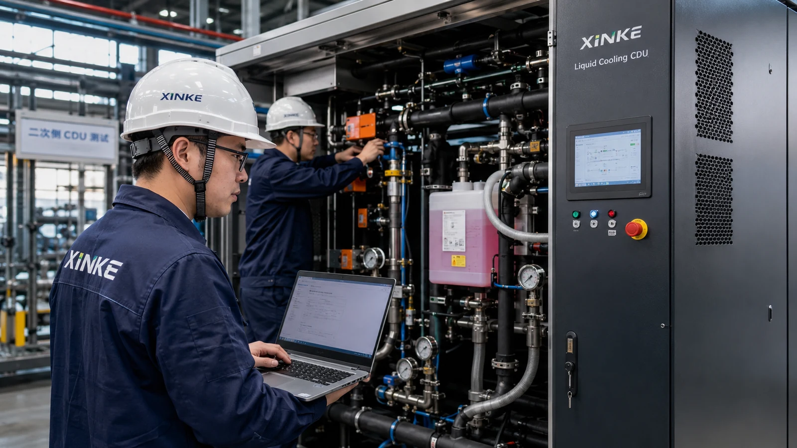
Commissioning is where a liquid-cooling design becomes an operating system. The process should prove that the loop is clean and leak-free, the pumps can deliver the required duty, the controls respond correctly, every alarm reaches the right operator, and the servers can be brought online without creating a hydraulic or thermal surprise.
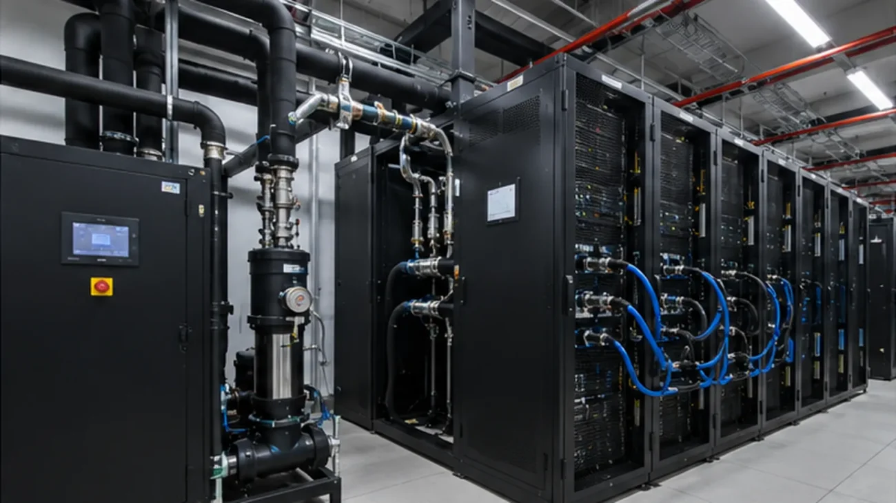
This checklist is written for direct-to-chip liquid-cooling projects involving a technology cooling system (TCS), one or more CDUs, rack manifolds, quick disconnects, and a facility-water system (FWS). It is a planning aid, not a replacement for the project’s approved method statements, safety plan, or manufacturer instructions.
Stage 1: Design and installation readiness
Before flushing or filling begins, confirm that the installed system matches the approved design and that the boundaries of responsibility are clear.
- Confirm the approved TCS and FWS temperatures, flows, pressures, coolant, and pressure-drop assumptions.
- Verify pipe and component material compatibility with the selected coolant.
- Check that valves, filters, strainers, drains, vents, gauges, and sensor locations are accessible for service.
- Record serial numbers, firmware versions, relay assignments, network addresses, and control-system points.
- Confirm the emergency stop, electrical isolation, spill response, and personal protective equipment procedures.
- Inspect supports, anchors, flexible hoses, drip protection, and cable routing around liquid components.
- Make sure a controlled water source, drainage point, coolant supply, and waste-handling method are available.
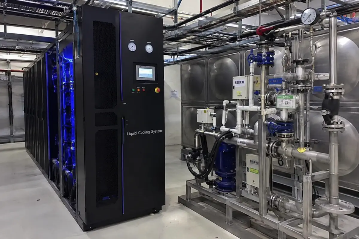
A common mistake is commissioning the CDU before checking the complete loop. The pump sees the whole circuit, including hoses, manifolds, quick disconnects, filters, valves, and cold plates. A CDU that performs well on its factory test rig may not reach the required flow in the installed system.
Stage 2: Flush, pressure-test, and prove cleanliness
Debris left after fabrication can block microchannels, damage pump seals, or settle in valves and heat exchangers. Flush the system using the approved sequence and verify cleanliness at the locations specified by the design.
Recommended checkpoints include:
- flush direction and velocity;
- temporary strainer mesh and inspection interval;
- particle count or cleanliness criterion where specified;
- air removal and venting procedure;
- pressure-test pressure, hold time, temperature, and acceptance criterion;
- documented inspection of accessible joints after pressure testing.
Pressure testing is not complete merely because the gauge did not move. Record the test medium, pressure, ambient conditions, stabilization time, test duration, leaks observed, repairs made, and final result.
Stage 3: Coolant fill and quality verification
Use only the approved coolant and concentration. Record the batch or product information, mix ratio, conductivity, pH, inhibitor condition, and fill volume required by the project.
After filling:
- vent the loop using the approved procedure;
- confirm pump rotation and minimum safe operating level;
- check for air entrainment, cavitation, and unstable differential pressure;
- inspect filters and strainers after initial circulation;
- record baseline coolant samples and sensor readings;
- verify that automatic make-up or pressure-control systems operate within their intended range.
Do not use a generic water-quality target without checking the coolant supplier, cold-plate manufacturer, CDU manufacturer, and project specification. The acceptable range depends on the chemistry and materials of the complete loop.
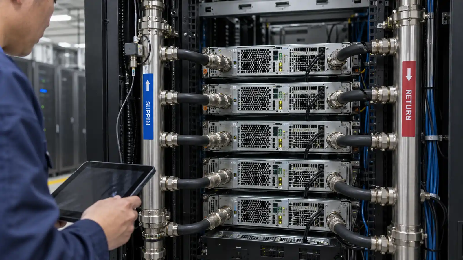
Stage 4: Hydraulic and thermal baseline
Establish a baseline with the server or thermal load simulator connected. Use stable operating points and record sufficient data to show that the system meets its design intent.
| Test area | What to record | Acceptance evidence |
|---|---|---|
| Secondary flow | Flow at each branch or rack point | Flow within approved tolerance |
| Differential pressure | Supply-to-return pressure at defined reference points | Meets control and server requirements |
| Supply temperature | CDU outlet and rack inlet | Temperature setpoint and stability achieved |
| Return temperature | Rack outlet and CDU return | Consistent with heat-load calculation |
| Pump performance | Speed, current, head, flow | Within approved pump and motor envelope |
| Facility boundary | FWS flow, pressure, and temperatures | CDU can maintain TCS conditions |
| Air side | Room temperature and component hotspots | Uncooled server heat is handled safely |
For a variable-speed system, test more than one operating point. Low-load response can be as important as full-load capacity because pumps and valves may become unstable when flow demand is small.
Stage 5: Controls, alarms, and failover
Controls commissioning should include both normal operation and abnormal conditions. Test each critical point from sensor input through the controller, BMS, alarm display, and operator response.
Exercise these scenarios:
- pump start, stop, ramp, and standby transfer;
- loss of a control valve signal;
- low differential pressure;
- high or low coolant temperature;
- low coolant level or abnormal make-up demand;
- facility-water flow or temperature excursion;
- BMS network interruption and recovery;
- leak alarm from each installed detector zone;
- power loss and controlled restart.
For every test, record the initiating stimulus, time to alarm, controller response, BMS response, local indication, and reset procedure. Alarm flooding can hide the one signal that matters, so verify alarm priority and messaging as well as the physical sensor.
Stage 6: Isolation and maintenance drills
Operators should practice the actions they will need during a real service event. Demonstrate rack isolation and return-to-service with the remaining load online. Check whether the controls maintain pressure and flow for the unaffected racks and whether the workload team receives a usable notice.
The drill should cover:
- identification of the rack and branch;
- valve operation and system response;
- drain, purge, and coupling procedure;
- coolant and spill handling;
- isolation of a failed pump or CDU;
- return to service, venting, and leak inspection.
If the system cannot be serviced without unacceptable flow changes, the design should be revised before the data center depends on it.
Stage 7: First AI workload
Treat the first live workload as a controlled ramp, not a one-click acceptance test. Begin at a low load and increase while monitoring rack inlet temperature, flow, pressure, pump response, leak sensors, and the air-side temperature of components not covered by cold plates.
Observe at least one representative transition from low to high load and back. Compare the measured response with the commissioning model and adjust control parameters only within approved limits.
Before full production, confirm that the operations team has:
- an up-to-date system diagram and valve schedule;
- recorded alarm limits and approved changes;
- spare quick disconnects, seals, sensors, filters, and fuses;
- an incident procedure for leaks, pump failure, and heat-rejection loss;
- a coolant sampling and trend-review schedule;
- a clear handover between facilities, IT, and controls teams.
At-a-glance checklist
- Design duty verified against installed pipework and server cold plates
- Flush and cleanliness evidence recorded
- Pressure test passed and joints inspected
- Coolant fill and baseline chemistry recorded
- Flow, pressure, and temperature tested at multiple load points
- Pump, valve, leak, BMS, and power-failure scenarios demonstrated
- Rack isolation drill completed
- First AI workload ramped with engineering support
- Spares, procedures, drawings, and training handed over
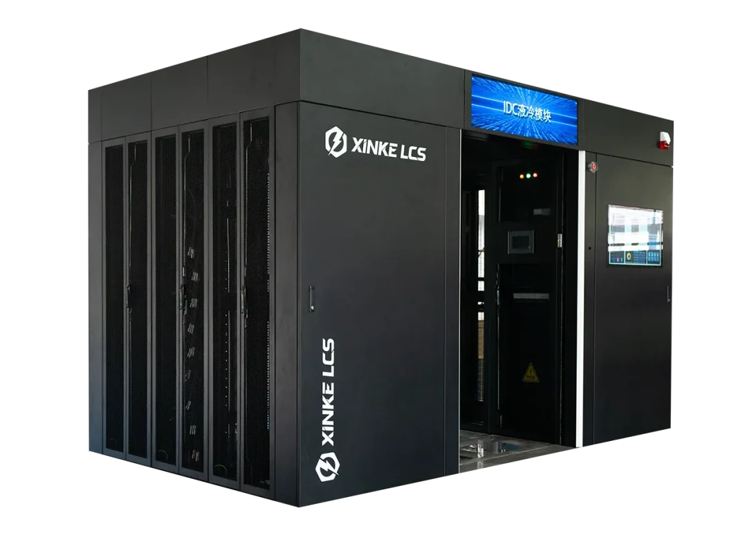
XINKE LCS can support the equipment and engineering conversation around rack-mounted CDUs, sidecar CDUs, in-row CDUs, and dry coolers. A useful commissioning plan starts with the server model, rack layout, fluid conditions, control protocol, redundancy requirement, and intended maintenance model.
Contact our engineering team to discuss a project-specific commissioning scope.