

How to Choose a CDU for High-Density GPU Racks

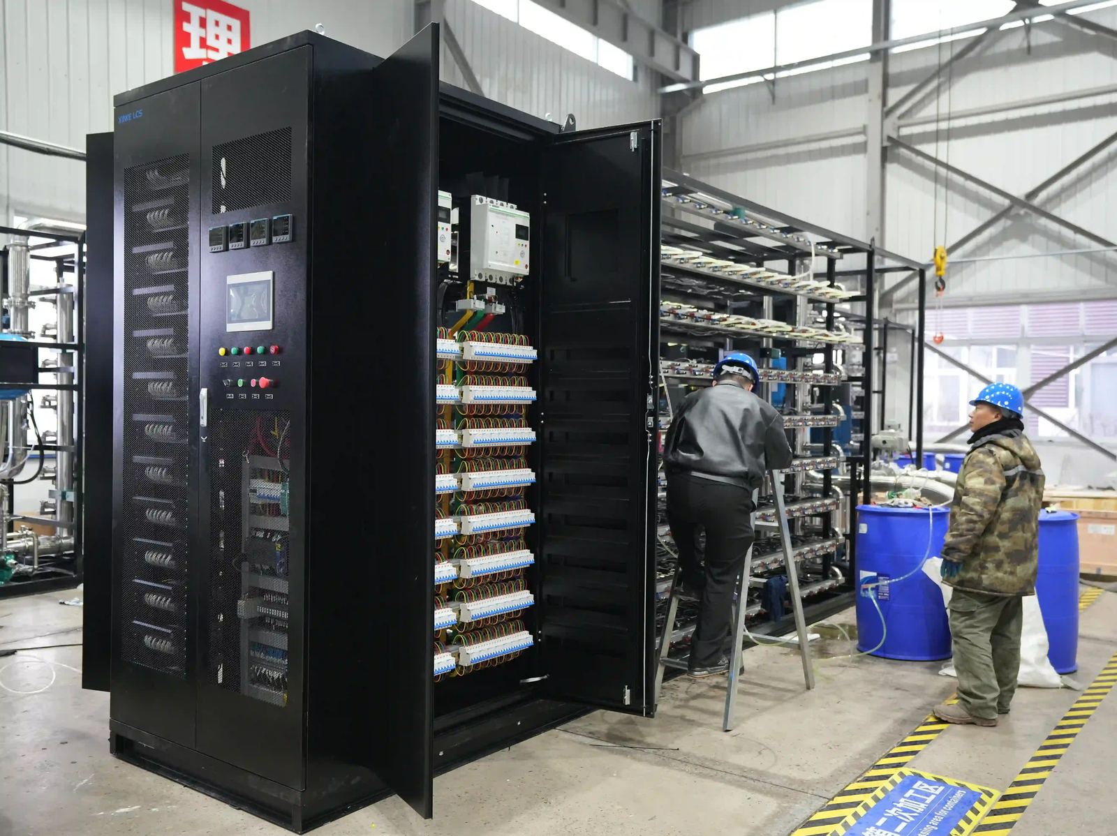
As AI training, inference, and HPC workloads push rack densities higher, selecting a CDU for GPU racks has become a system-engineering decision—not simply a question of matching a CDU’s kW rating to a rack’s nameplate power.
A CDU, or coolant distribution unit, must do much more than transfer heat. It must deliver stable coolant temperatures, provide sufficient flow to server cold plates, overcome the pressure losses of the secondary loop, integrate with the facility water system, and remain available when pumps, sensors, or power components require service.
A CDU that looks adequate on a datasheet can still create operational risk if its flow range, pump head, control strategy, or redundancy design does not match the GPU cluster. The right approach is to size the entire liquid-cooling loop first, then select the CDU around those real operating conditions.
Why CDU Selection Is More Than a kW Calculation
Cooling capacity remains important, but it is only one part of the decision.
The basic heat-transfer relationship is:
Q = m × Cp × ΔT
- Q is the heat load
- m is the coolant mass flow rate
- Cp is the coolant’s specific heat capacity
- ΔT is the temperature rise between CDU supply and return
In practical terms, a higher allowable coolant temperature rise can reduce the required flow rate. However, the allowable ΔT must remain within the inlet-temperature and flow limits defined by the server, GPU, CPU, cold plate, and rack-manifold design.
A complete CDU selection must therefore consider:
- Actual liquid-cooled IT heat load
- Supply and return temperature targets
- Required flow per rack and for the full cluster
- Total secondary-loop pressure drop
- Pump curve and control range
- Facility-water conditions
- Redundancy and maintenance requirements
- Monitoring, alarms, and building-management integration
Step 1: Define the Real Rack Heat Load
Do not start with only the rack’s maximum electrical rating. Start by identifying how much of that heat actually enters the liquid loop.
A modern GPU rack may contain liquid-cooled GPUs and CPUs while retaining air-cooled memory, storage, switches, power equipment, or auxiliary devices. The CDU needs to cover the heat transferred to the coolant—not necessarily every watt consumed by the rack.
| Input | Why It Matters | Questions to Ask |
|---|---|---|
| Rack IT load | Establishes the thermal starting point | What is the peak and typical rack load? |
| Liquid-cooled load | Defines CDU duty | Which components are connected to the coolant loop? |
| Growth plan | Avoids near-term undersizing | Will GPU count or rack density increase? |
| Simultaneous peak load | Sets the real design case | Will every rack run at maximum load simultaneously? |
| Residual air cooling | Affects room-cooling design | What heat remains in the white space? |
It is also important to separate steady-state operation from short-duration peak demand. A facility may not need to size every component for an unlikely simultaneous maximum, but it should have a clear operating assumption approved by both the IT and facilities teams.
Step 2: Select Capacity with a Practical Design Margin
Once the liquid-cooled heat load is known, calculate the CDU’s required duty under realistic operating conditions.
For example, if a GPU cluster transfers 500 kW of heat to the liquid loop, the engineering team may select additional capacity for expansion, transient loading, and performance variation. The exact margin depends on the deployment strategy, redundancy architecture, and whether additional CDU modules can be installed later.
This is an illustrative example only. Final capacity must be confirmed through equipment data, temperature conditions, and hydraulic design.
When comparing CDU capacity, ask vendors to define exactly what their rating means:
- At what primary-side and secondary-side temperatures is the capacity measured?
- Is the rating based on water or a glycol-water mixture?
- What flow rates are assumed on each side of the heat exchanger?
- Does the published capacity include fouling allowance?
- Is the rating available continuously or only at a specific point on the performance curve?
For evolving AI deployments, a modular CDU architecture can be attractive. Instead of installing one large unit with excess capacity from day one, a site may add capacity in stages as racks are commissioned.
Step 3: Size Coolant Flow from Allowable Temperature Rise
The CDU must provide enough flow to carry heat away while maintaining the required coolant inlet temperature to the IT equipment.
A lower secondary-loop ΔT generally requires more coolant flow. More flow may improve temperature uniformity, but it can also increase pumping energy, pressure drop, pipe size, and the demand placed on valves and quick-disconnects.
| Lower Coolant ΔT | Higher Coolant ΔT |
|---|---|
| Requires higher flow | Requires lower flow |
| May improve temperature uniformity | May improve pumping efficiency |
| Can increase pump power and pressure drop | Requires careful validation of IT inlet limits |
| May require larger distribution components | May reduce pipe and pump sizing requirements |
The correct target is determined by the server OEM’s requirements and the rack-level liquid-distribution design. Every cold plate, manifold, flexible hose, and quick-disconnect contributes to the final operating condition.
Step 4: Build a Pressure-Drop Budget Before Choosing Pumps
For a CDU for GPU racks, pressure drop is often the most underestimated selection factor.
The CDU pump must overcome the resistance of the complete secondary circuit—not merely the pressure loss inside the CDU. Every component between the CDU outlet and return adds resistance.
Build a pressure-drop budget that includes:
- GPU and CPU cold plates
- Rack manifolds
- Supply and return piping
- Flexible hoses
- Quick-disconnect couplings
- Isolation and balancing valves
- Filters and strainers
- Heat exchangers
- Flow meters and sensors
- Elevation effects, where applicable
- Allowance for filter loading and system aging
| Secondary-Loop Component | Pressure Drop at Design Flow | Verification Method |
|---|---|---|
| Server cold plates | [Enter value] | Server OEM hydraulic data |
| Rack manifold | [Enter value] | Manifold supplier data |
| Quick-disconnects | [Enter value] | Coupling performance curve |
| Hoses and piping | [Enter value] | Pipe calculation |
| Valves and fittings | [Enter value] | Valve or fitting Kv/Cv data |
| Filters | [Enter value] | Clean and dirty filter conditions |
| CDU internal circuit | [Enter value] | CDU supplier data |
| Total required pump head | [Total] | Final hydraulic review |
The final operating point must sit on the pump curve with appropriate margin. It should also remain stable at partial load, reduced rack count, and changing valve positions.
Variable-frequency drives can allow pumps to respond to real operating conditions. Depending on the system architecture, pumps may control against differential pressure, flow, temperature, or a coordinated logic strategy.
Step 5: Choose the Right Redundancy Architecture
Redundancy should be selected according to the business impact of lost cooling capacity.
| Architecture | Best For | Benefits | Trade-Offs |
|---|---|---|---|
| N | Lower-criticality or cost-sensitive deployments | Lowest first cost and simple design | Maintenance or failure can reduce cooling availability |
| N+1 | Most production AI/HPC deployments | Supports one additional component or module | Requires disciplined sizing and maintenance |
| 2N | Highly critical environments | Independent duplicate capacity path | Higher cost, footprint, and complexity |
Redundancy should not stop at pumps. Consider whether the project requires redundancy for:
- Primary and secondary pumps
- Pump power supplies and electrical feeds
- Heat-exchanger capacity
- Controllers and communication paths
- Temperature and pressure sensors
- Leak-detection devices
- Network connectivity to BMS or DCIM
Also distinguish between redundancy and maintainability. A system may include a standby pump yet still require shutdown to isolate and replace a component.
Step 6: Check Facility-Side Compatibility
The CDU sits between IT equipment and the facility cooling infrastructure. It must work properly with both.
Before final selection, document:
- Available supply-water temperature across all seasons
- Expected return-water temperature
- Primary-loop pressure and available differential pressure
- Water chemistry, filtration, and treatment program
- Glycol concentration, if used
- Material compatibility and corrosion-control requirements
- Water availability and heat-rejection strategy
- Connection sizes, pipe routing, and service clearances
A CDU that performs well with cool facility water may deliver reduced capacity if the site experiences higher entering-water temperatures during summer operation. The design team should review the worst expected operating condition, not only the ideal condition.
For water-constrained or harsh climates, heat-rejection selection may also affect CDU strategy. XINKE LCS provides liquid-cooling solutions that can be adapted to different site conditions, including dry coolers and closed cooling systems.
Learn about XINKE LCS liquid-cooling technologies
Step 7: Evaluate CDU Controls, Alarms, and Data Integration
At GPU-rack densities, CDU controls are part of the uptime strategy.
A suitable control system should support:
- Supply-temperature control
- Differential-pressure or flow control
- Variable-speed pump operation
- High-temperature and low-flow alarms
- Leak-detection input and response logic
- Sensor fault detection
- Pump lead-lag rotation
- Trend logging and commissioning data
- Remote monitoring
- BMS, DCIM, or site-control integration
Ask how the CDU responds to abnormal conditions:
- What happens if a pump fails?
- What is the alarm sequence if supply temperature rises?
- Can the system identify a blocked filter or abnormal pressure loss?
- Are alarms visible remotely?
- Can operating data be integrated through the project’s preferred protocol?
XINKE LCS highlights intelligent temperature control, remote management, leak detection, and customized liquid-cooling configurations as part of its solution approach.
CDU Selection Checklist for GPU Rack Projects
Before requesting a quotation, prepare the following information:
- Number of racks and current/future rack heat load
- GPU, CPU, and server platform
- Percentage of rack heat transferred to liquid
- Required supply and return temperatures
- Required flow range per rack and for the cluster
- Secondary-loop pressure-drop budget
- Pipe routing and approximate loop length
- Facility-water temperatures and pressure conditions
- Water-quality requirements
- Redundancy target: N, N+1, or 2N
- Required monitoring, alarms, and BMS/DCIM protocol
- Site constraints, including footprint, access, noise, and service space
- Deployment schedule and expansion plan
When to Request a Custom CDU Design
A standard configuration may be appropriate for repeatable deployments. However, a custom CDU design is often justified when the project includes unusually high rack density, long secondary loops, mixed server generations, strict uptime objectives, containerized infrastructure, edge locations, heat-reuse requirements, or unusual facility-water conditions.
A customized approach can align interfaces, pump performance, controls, physical dimensions, cooling method, and monitoring requirements with the actual site.
Discuss a customized liquid-cooling solution with XINKE LCS
Choose the CDU as a System, Not a Standalone Box
The right CDU for GPU racks is selected by matching capacity, coolant flow, pressure drop, controls, facility conditions, and redundancy requirements across the full liquid-cooling loop.
A kW rating is only the starting point. The more accurately you define the rack heat load, temperature window, hydraulic resistance, and operational risk tolerance, the more reliable and efficient the final solution will be.
For a GPU liquid-cooling project, provide XINKE LCS with your rack count, per-rack heat load, server platform, target temperatures, piping layout, estimated pressure drop, facility-water conditions, and redundancy target. This allows the engineering team to evaluate the complete cooling architecture and recommend an appropriate CDU solution.
Frequently Asked Questions
What does a CDU do in a GPU rack liquid-cooling system?
A CDU transfers heat from the IT-side coolant loop to the facility-side cooling loop. It typically manages heat exchange, pumping, temperature control, pressure or flow control, monitoring, and alarms.
How do I calculate required CDU flow?
Flow is calculated from the liquid-cooled heat load, coolant properties, and allowed coolant temperature rise. The final flow must also comply with the flow requirements of the servers, cold plates, manifolds, and quick-disconnects.
Why is pressure drop important when choosing a CDU?
The CDU pumps must overcome resistance from all components in the secondary loop. If available pump head is insufficient, the system may not deliver the required flow to the racks. If it is excessive, it may cause unstable control or unwanted stress on components.
Is N+1 redundancy enough for an AI GPU cluster?
N+1 is often suitable for production deployments, but the correct architecture depends on the cost of downtime, maintenance strategy, component-level redundancy, and whether the site requires concurrent maintainability.
What information should I send to a CDU supplier?
Provide the heat load, rack count, server platform, coolant temperature targets, required flow, estimated pressure drop, facility-water conditions, redundancy target, monitoring requirements, site constraints, and expansion plan.