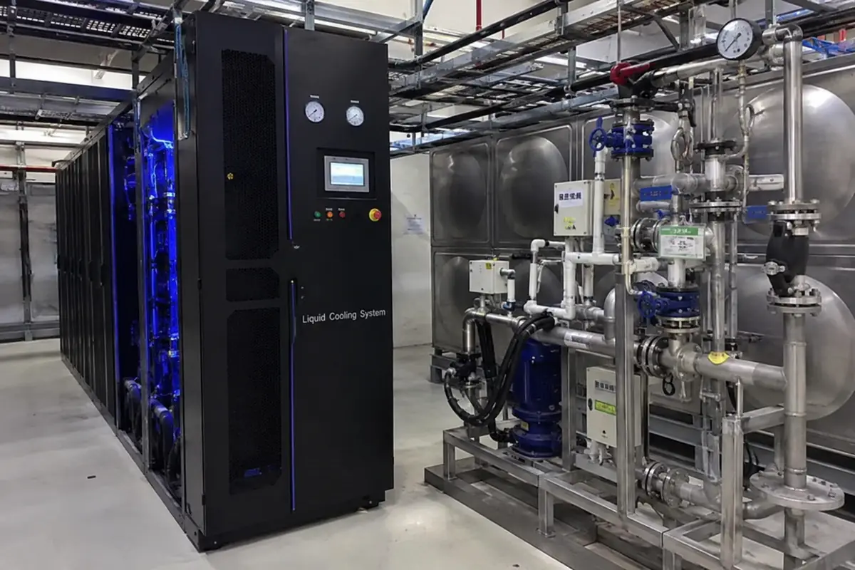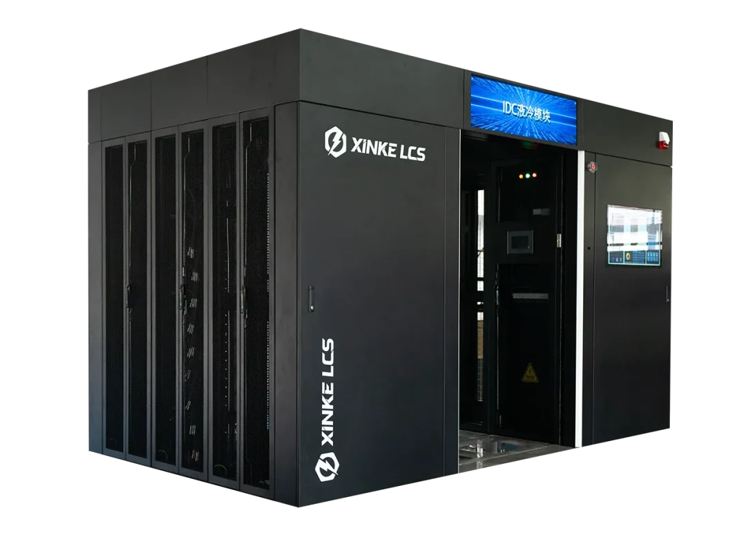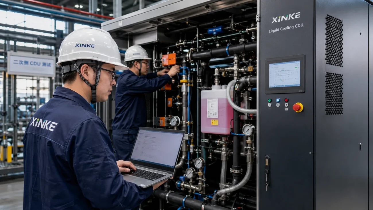

Why a CDU Alone Does Not Make a Liquid-Cooling System Reliable

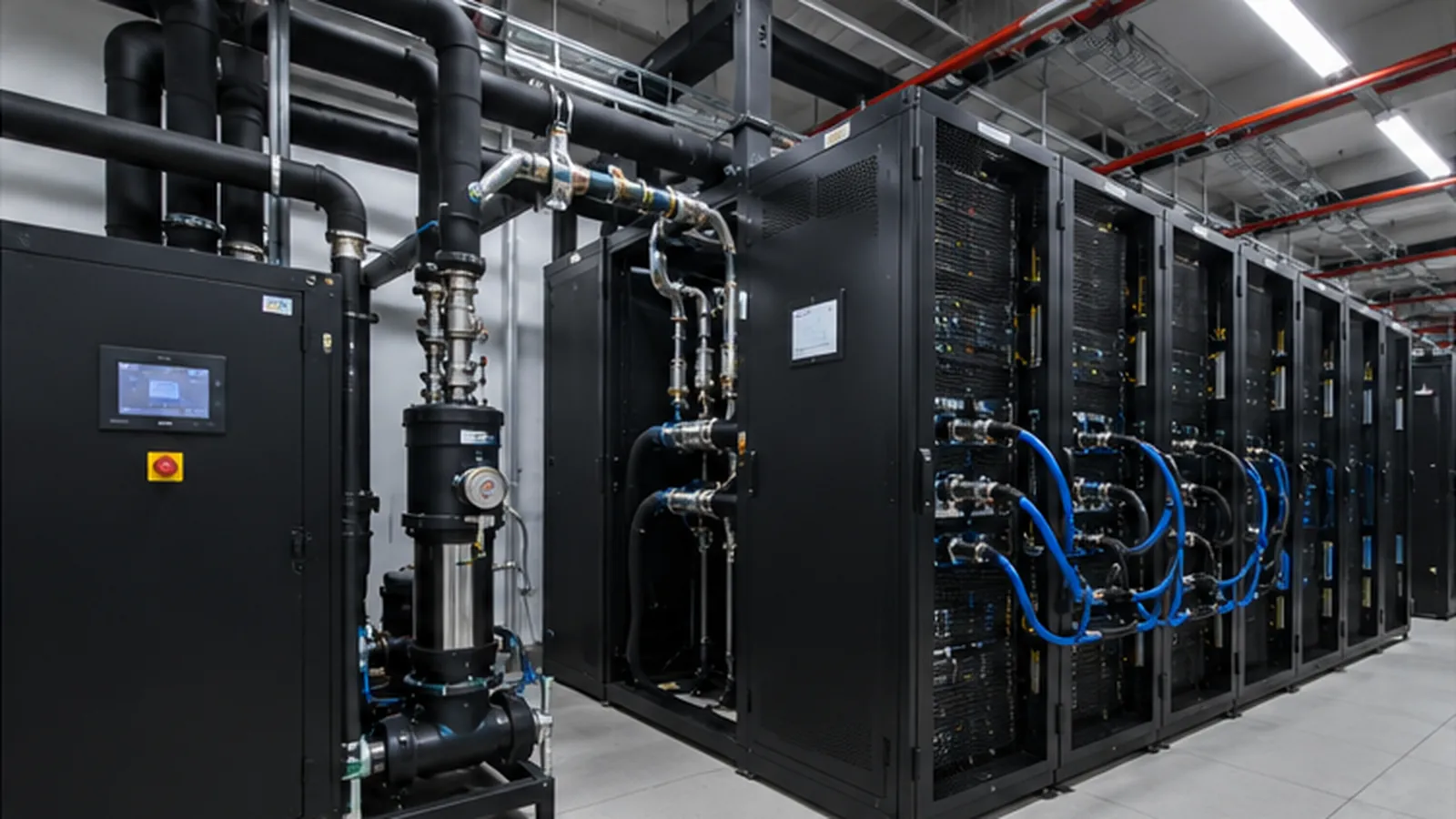
A data center can purchase a correctly sized coolant distribution unit (CDU), install it on schedule, and still end up with an unreliable liquid-cooling system. The reason is simple: a CDU is one component in a control and hydraulic network that includes cold plates, manifolds, quick disconnects, pumps, valves, sensors, facility water, heat rejection, and the building management system (BMS).
For AI infrastructure, reliability is not only a question of whether the CDU can remove enough heat under steady conditions. It is also a question of whether the entire system can preserve flow and temperature stability when a rack is isolated for service, a pump changes speed, an AI training job starts or stops, a sensor drifts, or a small leak appears at a connection.
Capacity is a starting point, not an operating strategy
Two CDUs may carry the same nominal cooling-capacity rating and behave very differently in the same data center. The useful comparison must include the supply and return temperatures, coolant type, required flow, system pressure drop, redundancy architecture, and facility-water conditions.
Once the unit is operating, however, a second set of questions becomes more important:
- How quickly does the CDU respond to a sudden reduction or increase in rack load?
- Can it maintain differential pressure across the secondary loop while pumps modulate?
- Does the BMS know which rack valve should compensate when another rack is isolated?
- Can a leak alarm trigger the correct sequence of alarms, valve actions, and workload decisions?
- Can operators distinguish a normal transient from the beginning of a pump, filter, or coolant problem?
Those functions live across the control hierarchy, not inside the CDU alone. This is why adding more nameplate capacity does not automatically produce a more resilient design.
1. The control layer must match the physical system
A liquid-cooling control system should be designed from the heat source outward. The control logic needs to know what the servers can tolerate, what the facility can supply, and which valves or pumps can act without creating a new hydraulic problem.
At minimum, the control architecture should collect and trend:
- CDU primary and secondary supply and return temperatures;
- secondary-loop flow and differential pressure;
- pump speed, current, status, and fault signals;
- facility-water temperature and pressure at the CDU boundary;
- rack or manifold valve position where available;
- leak-sensor state and detector-zone identity;
- coolant conductivity, pressure, and other quality indicators specified by the project.
The point is not to create a large dashboard. Each measurement should support a defined action, alarm, trend calculation, or maintenance decision. A sensor without an operating response can add complexity without improving reliability.
2. Isolating one rack must not destabilize the others
Maintenance isolation is a practical test of system resilience. When one rack is disconnected, its flow is removed from the shared loop. Without suitable compensation, the remaining online racks may see a pressure rise or a change in flow distribution.
A robust design usually combines several measures:
- defined isolation valves at rack or manifold level;
- pressure-independent balancing or control valves where required;
- pump control that can respond to the actual system curve;
- engineered bypass capacity for a minimum number of isolated racks;
- a written sequence for closing, purging, coupling, and reopening a rack;
- alarm limits that distinguish a planned flow change from an unexpected one.
The operating team should demonstrate the response during commissioning, not discover it during the first live maintenance event. Record the pressure, flow, valve position, pump speed, and rack inlet temperature before, during, and after isolation.
3. Leak response should be automatic, local, and explainable
Leak protection is more than installing sensors below a rack. A complete response needs to identify the detector zone, notify the BMS, isolate the affected branch when the design permits, maintain cooling for unaffected racks, and give operators a clear sequence for inspection and restart.
A practical response hierarchy can be organized as follows:
| Level | Response | Design question |
|---|---|---|
| Detection | Alarm at the correct leak-detector zone | Can the operator locate the fault without searching the entire row? |
| Containment | Stop additional liquid from entering the affected branch | Which valve can close safely, and what happens to flow elsewhere? |
| Isolation | Protect adjacent racks and electrical areas | Does the isolation action create an unsafe pressure transient? |
| Workload coordination | Drain, migrate, pause, or shut down the affected job | Which decision belongs to the cooling system, and which belongs to IT operations? |
| Recovery | Repair, verify, refill, vent, and restart | What evidence is required before the rack is returned to service? |
The automation boundary must be explicit. A valve closing automatically may be appropriate for one architecture and unsafe for another. The design team should define what the control system may change without operator approval and what must be coordinated with the workload scheduler.
4. AI loads make stable control more important
AI workloads can move between idle, training, checkpointing, and inference states, creating large changes in heat output. The cooling system does not need to follow every millisecond of software activity, but it does need to keep coolant temperature and flow inside the server envelope as the average load changes.
Useful control objectives include:
- maintaining the specified rack inlet temperature during load transitions;
- preventing pump hunting when flow demand changes;
- coordinating secondary-loop control with the facility-water source;
- holding stable differential pressure across online racks;
- using load forecasts or rate limits where the supported server platform provides them.
A digital model can help the design team compare control strategies before deployment. A model is not a substitute for real commissioning, but it can reveal hydraulic interactions that would be difficult to see in a static design spreadsheet.
5. Commission the system as a system
The acceptance plan should cover the complete heat path, not only the CDU. A strong commissioning sequence includes flushing, pressure testing, coolant verification, pump and valve response, control-loop tuning, alarm testing, redundancy transfer, and a controlled heat-load test.
Include these scenarios in the witnessed test program:
- loss of one pump;
- transfer to the standby CDU or pump set;
- planned isolation of one rack;
- unexpected drop in secondary-loop pressure;
- facility-water temperature or flow excursion;
- false and real leak-alarm responses;
- BMS communication loss and recovery.
Acceptance criteria should be measured and recorded. “The alarm worked” is weaker than recording the alarm source, time to BMS notification, valve response, resulting flow change, and return-to-normal sequence.
Operations: the system is only reliable if it can be diagnosed
Long-term reliability depends on trend data and serviceability. Operators should be able to see whether a change in pump speed is caused by a rack valve, a blocked strainer, a rising system pressure drop, or a change in the facility-water boundary conditions.
Define alarm priorities, response times, spare parts, and maintenance intervals before handover. Track coolant condition, strainer differential pressure, pump performance, sensor drift, valve travel, and quick-disconnect condition as part of the preventive-maintenance program.
The practical takeaway
A CDU can deliver the specified capacity in a factory test and still be part of an unreliable installation. The distinction is whether the project treats liquid cooling as a coordinated thermal, hydraulic, electrical, controls, and operations system.
The best acceptance question is not “Does the CDU meet its rated capacity?” but “Can the complete system keep every online rack within specification while one component is isolated, one fault is introduced, or one load changes?”
XINKE LCS supplies rack-mounted CDUs, enclosure-side CDUs, high-power in-row CDUs, and air-cooled heat-rejection equipment for data-center projects. For a system-level review, share the rack layout, server thermal requirements, facility-water conditions, control protocol, redundancy target, and maintenance strategy with our engineering team.
Contact XINKE LCS for a project-specific liquid-cooling design review.